Configuring bfd for is-is, Network requirements – H3C Technologies H3C SR8800 User Manual
Page 354
338
Flag : R/-/- Cost : 10
Next Hop : FE80::20F:E2FF:FE3E:FA3D Interface: S2/1/3
Flags: D-Direct, R-Added to RM, L-Advertised in LSPs, U-Up/Down Bit Set
# Display the IPv6 IS-IS routing table of Router D.
[RouterD] display isis route ipv6
Route information for ISIS(1)
-----------------------------
ISIS(1) IPv6 Level-2 Forwarding Table
-------------------------------------
Destination: 2001:1:: PrefixLen: 64
Flag : R/-/- Cost : 20
Next Hop : FE80::200:FF:FE0F:4 Interface: S2/1/1
Destination: 2001:2:: PrefixLen: 64
Flag : R/-/- Cost : 20
Next Hop : FE80::200:FF:FE0F:4 Interface: S2/1/1
Destination: 2001:3:: PrefixLen: 64
Flag : D/L/- Cost : 10
Next Hop : Direct Interface: S2/1/1
Destination: 2001:4::1 PrefixLen: 128
Flag : D/L/- Cost : 0
Next Hop : Direct Interface: GE1/1/1
Flags: D-Direct, R-Added to RM, L-Advertised in LSPs, U-Up/Down Bit Set
Configuring BFD for IS-IS
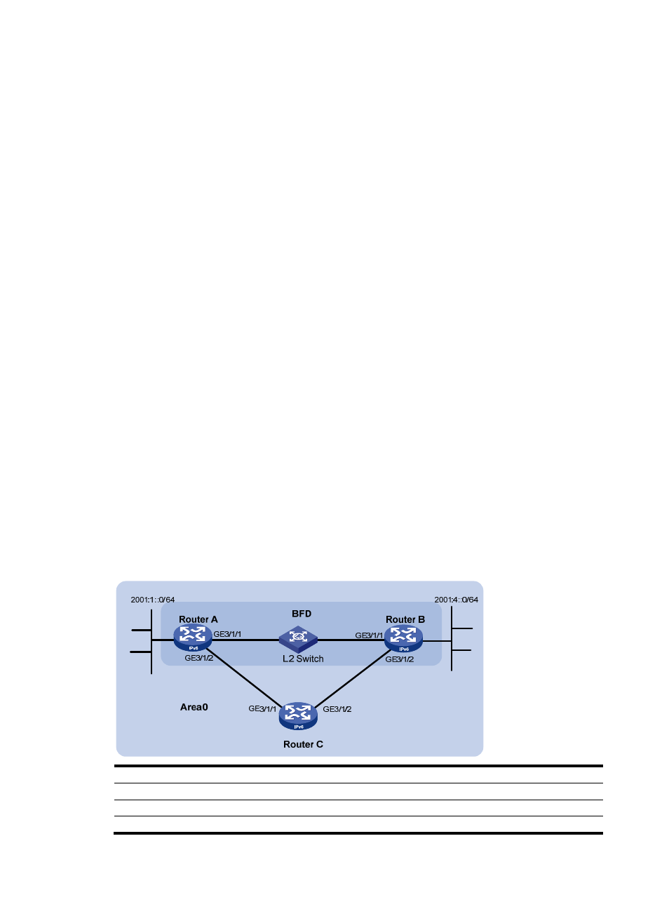
Network requirements
•
As shown in
, configure IPv6 IS-IS on Router A, Router B and Router C and configure BFD
over the link Router A<—>L2 Switch<—>Router B.
•
After the link between Router B and the Layer-2 switch fails, BFD can quickly detect the failure and
notify IPv6 IS-IS of the failure. Then Router A and Router B communicate through Router C.
Figure 116 Network diagram
Device Interface IPv6
address
Device
Interface
IPv6 address
Router A
GE3/1/1
2001::1/64
Router B
GE3/1/1
2001::2/64
GE3/1/2
2001:2::1/64
GE3/1/2 2001:3::2/64
Router C
GE3/1/1
2001:2::2/64
- H3C SR6600-X H3C SR6600 H3C WX6000 Series Access Controllers H3C WX5000 Series Access Controllers H3C WX3000 Series Unified Switches H3C LSWM1WCM10 Access Controller Module H3C LSWM1WCM20 Access Controller Module H3C LSQM1WCMB0 Access Controller Module H3C LSRM1WCM2A1 Access Controller Module H3C LSBM1WCM2A0 Access Controller Module