Configuring an ospf stub area, Network requirements, Configuration procedure – H3C Technologies H3C SR8800 User Manual
Page 129
113
10.2.1.0/24 O_ASE 150 1 11.2.1.1 GE3/1/1
10.3.1.0/24 O_ASE 150 1 11.2.1.1 GE3/1/1
10.4.1.0/24 O_ASE 150 1 11.2.1.1 GE3/1/1
11.2.1.0/24 Direct 0 0 11.2.1.2 GE3/1/1
11.2.1.2/32 Direct 0 0 127.0.0.1 InLoop0
127.0.0.0/8 Direct 0 0 127.0.0.1 InLoop0
127.0.0.1/32 Direct 0 0 127.0.0.1 InLoop0
5.
Configure summary route 10.0.0.0/8 on Router B and advertise it:
[RouterB-ospf-1] asbr-summary 10.0.0.0 8
# Display the routing table of Router A.
[RouterA] display ip routing-table
Routing Tables: Public
Destinations : 5 Routes : 5
Destination/Mask Proto Pre Cost NextHop Interface
10.0.0.0/8 O_ASE 150 2 11.2.1.1 GE3/1/1
11.2.1.0/24 Direct 0 0 11.2.1.2 GE3/1/1
11.2.1.2/32 Direct 0 0 127.0.0.1 InLoop0
127.0.0.0/8 Direct 0 0 127.0.0.1 InLoop0
127.0.0.1/32 Direct 0 0 127.0.0.1 InLoop0
The output shows that routes 10.1.1.0/24, 10.2.1.0/24, 10.3.1.0/24 and 10.4.1.0/24 are
summaried into one route 10.0.0.0/8.
Configuring an OSPF stub area
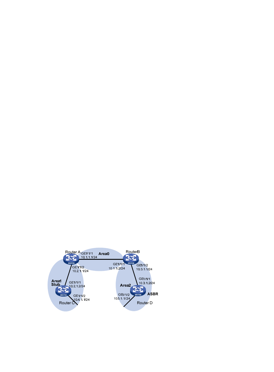
Network requirements
shows an AS is split into three areas, where all routers run OSPF. Router A and Router B act as
ABRs to forward routing information between areas. Router D acts as the ASBR and is enabled to
redistribute static routes.
Configure Area 1 as a Stub area, reducing LSAs to this area without influencing route reachability.
Figure 41 OSPF Stub area configuration
Configuration procedure
1.
Configure IP addresses for interfaces. (Details not shown)
- H3C SR6600-X H3C SR6600 H3C WX6000 Series Access Controllers H3C WX5000 Series Access Controllers H3C WX3000 Series Unified Switches H3C LSWM1WCM10 Access Controller Module H3C LSWM1WCM20 Access Controller Module H3C LSQM1WCMB0 Access Controller Module H3C LSRM1WCM2A1 Access Controller Module H3C LSBM1WCM2A0 Access Controller Module