Bgp load balancing configuration example, Network requirements, Configuration procedure – H3C Technologies H3C SR8800 User Manual
Page 261
245
Reply from 9.1.2.1: bytes=56 Sequence=3 ttl=254 time=47 ms
Reply from 9.1.2.1: bytes=56 Sequence=4 ttl=254 time=46 ms
Reply from 9.1.2.1: bytes=56 Sequence=5 ttl=254 time=47 ms
--- 9.1.2.1 ping statistics ---
5 packet(s) transmitted
5 packet(s) received
0.00% packet loss
round-trip min/avg/max = 15/37/47 ms
[RouterC] ping -a 9.1.2.1 8.1.1.1
PING 8.1.1.1: 56 data bytes, press CTRL_C to break
Reply from 8.1.1.1: bytes=56 Sequence=1 ttl=254 time=2 ms
Reply from 8.1.1.1: bytes=56 Sequence=2 ttl=254 time=2 ms
Reply from 8.1.1.1: bytes=56 Sequence=3 ttl=254 time=2 ms
Reply from 8.1.1.1: bytes=56 Sequence=4 ttl=254 time=2 ms
Reply from 8.1.1.1: bytes=56 Sequence=5 ttl=254 time=2 ms
--- 8.1.1.1 ping statistics ---
5 packet(s) transmitted
5 packet(s) received
0.00% packet loss
round-trip min/avg/max = 2/2/2 ms
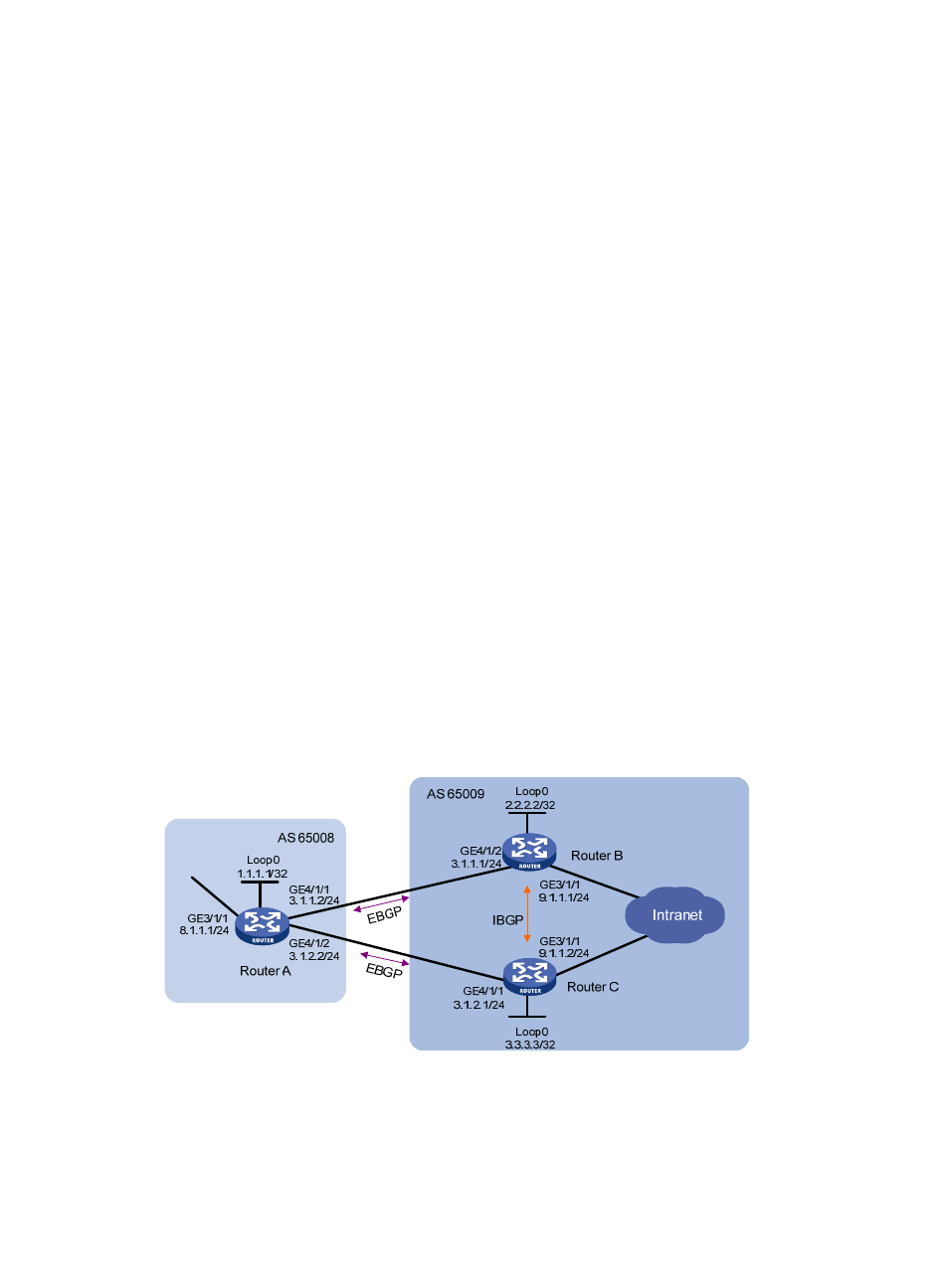
BGP load balancing configuration example
Network requirements
This example describes how to configure BGP load balancing.
As shown in
, all routers run BGP, and Router A resides in AS 65008, Router B and Router C in
AS 65009. Between Router A and Router B, Router A and Router C are EBGP connections, and between
Router B and Router C is an IBGP connection. Two routes are configured on Router A for load balancing.
Figure 92 Network diagram
Configuration procedure
1.
Configure IP addresses for interfaces. (Details not shown)
2.
Configure BGP connections:
- H3C SR6600-X H3C SR6600 H3C WX6000 Series Access Controllers H3C WX5000 Series Access Controllers H3C WX3000 Series Unified Switches H3C LSWM1WCM10 Access Controller Module H3C LSWM1WCM20 Access Controller Module H3C LSQM1WCMB0 Access Controller Module H3C LSRM1WCM2A1 Access Controller Module H3C LSBM1WCM2A0 Access Controller Module