Configuration procedure, Figure 98 network diagram – H3C Technologies H3C SR8800 User Manual
Page 276
260
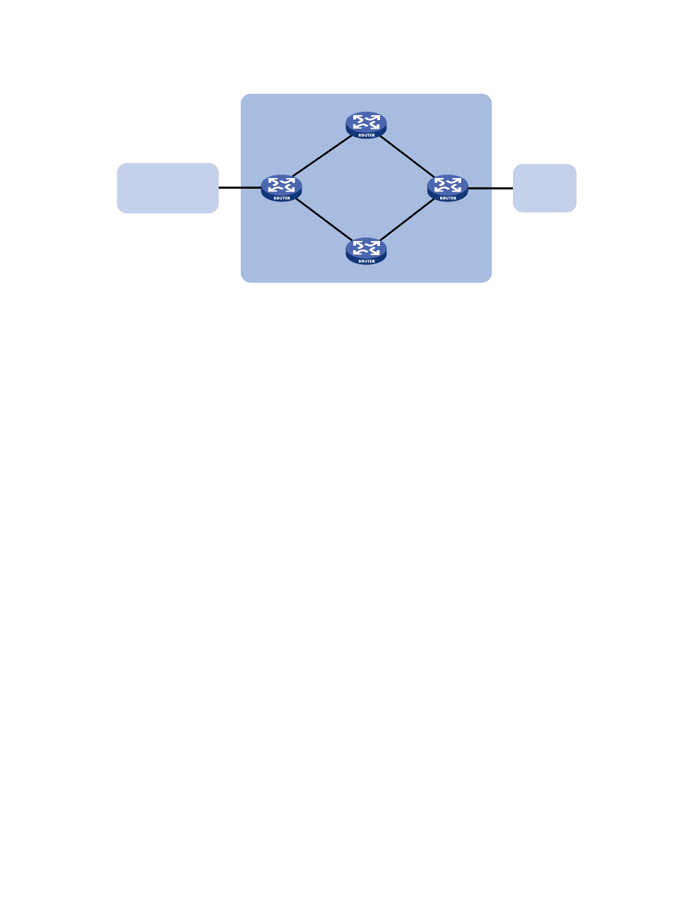
Figure 98 Network diagram
Configuration procedure
1.
Configure IP addresses for interfaces. (Details not shown)
2.
Configure OSPF so that Router A and Router C are reachable to each other. (Details not shown)
3.
Configure BGP on Router A:
# Establish two IBGP connections between Router A and Router C.
[RouterA] bgp 200
[RouterA-bgp] peer 3.0.2.2 as-number 200
[RouterA-bgp] peer 2.0.2.2 as-number 200
[RouterA-bgp] quit
# When the two links between Router A and Router C are both up, Router C adopts the link Router
A<—>Router B<—>Router C to exchange packets with network 1.1.1.0/24. (Set a higher MED
value for route 1.1.1.0/24 sent to peer 2.0.2.2 on Router A.)
{
Create ACL 2000 to permit 1.1.1.0/24 to pass.
[RouterA] acl number 2000
[RouterA-acl-basic-2000] rule permit source 1.1.1.0 0.0.0.255
[RouterA-acl-basic-2000] quit
{
Create two route policies, apply_med_50 and apply_med_100. Policy apply_med_50 sets the
MED for route 1.1.1.0/24 to 50. Policy apply_med_100 sets that to 100.
[RouterA] route-policy apply_med_50 permit node 10
[RouterA-route-policy] if-match acl 2000
[RouterA-route-policy] apply cost 50
[RouterA-route-policy] quit
[RouterA] route-policy apply_med_100 permit node 10
[RouterA-route-policy] if-match acl 2000
[RouterA-route-policy] apply cost 100
[RouterA-route-policy] quit
{
Apply routing policy apply_med_50 to routes outgoing to peer 3.0.2.2, and apply routing
policy apply_med_100 to routes outgoing to peer 2.0.2.2.
[RouterA] bgp 200
[RouterA-bgp] peer 3.0.2.2 route-policy apply_med_50 export
[RouterA-bgp] peer 2.0.2.2 route-policy apply_med_100 export
2.0.1. 1/ 24
2. 0.2.2/24
Router A
Router C
AS 200
Router D
2. 0.1.2/24
2. 0. 2.1/24
3. 0.1.1/24
3. 0.1.2/24
3.0.2. 1/ 24
3.0.2. 2/ 24
Router B
AS 100
AS 300
1. 1.1.0/24
GE3/1/2
GE3/1/1
GE3/1/1
GE3/1/1
GE3/1/1
GE3/1/2
GE3/1/2
GE3/1/2
- H3C SR6600-X H3C SR6600 H3C WX6000 Series Access Controllers H3C WX5000 Series Access Controllers H3C WX3000 Series Unified Switches H3C LSWM1WCM10 Access Controller Module H3C LSWM1WCM20 Access Controller Module H3C LSQM1WCMB0 Access Controller Module H3C LSRM1WCM2A1 Access Controller Module H3C LSBM1WCM2A0 Access Controller Module