Dial-out, Dial-in, Rs-485 setup (optional) – Winco DGC-2020 User Manual
Page 90: Rs-485 setup (optional) -20, Figure 4-18. modem setup -20
Overspeed
Alarm
Scheduled Maintenance Pre-Alarm
Switch Not in Auto
Transfer Fail Alarm
Virtual Output X Status (X = 1 to 8)
Weak Battery Voltage Pre-Alarm
Dial-Out
The DGC-2020 uses telelocator alphanumeric protocol (TAP) version 1.7 when communicating with
paging companies. This data format
D
specifies seven data bits with even parity. If required, eight data bits
with no parity may be specified.
The message string sent by the DGC-2020 can be limited to a length supported by the receiving pagers
E
.
If a message to be transmitted by the DGC-2020 exceeds the pager message limit, the DGC-2020 will
make multiple calls to transmit the complete message.
Dial-out messages are sent by the DGC-2020 at a user-defined interval
F
. This interval gives an operator
the opportunity to dial into the DGC-2020. A second user-defined interval
G
determines how frequently
dial-out attempts are made following a dial-out failure.
Dial-In
When the DGC-2020 modem shares a line used for voice communication, the number of rings
H
required
for the modem to answer can be increased to allow time for an operator to answer an incoming telephone
call.
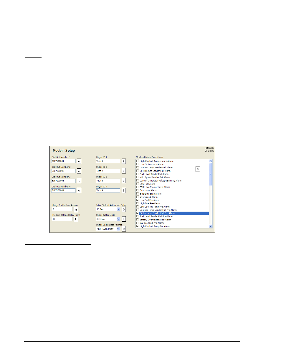
Figure 4-18. Modem Setup
A
Dial Out Number: Accepts a telephone number of up to 16 characters.
B
Pager ID: Accepts a pager identification number of up to 16 characters.
C
Modem Dialout Conditions: Check boxes to select conditions that will initiate a dial-out message.
D
Pager Coms Data Format: 7 bit – Even Parity or 8 bit – No Parity.
E
Pager Buffer Limit: Adjustable from 80 to 200 characters in increments of 40.
F
Modem Offline Delay: Adjustable from 1 to 240 min in 1 min increments.
G
Inter Dialout Activation Delay: A delay of 15, 30, 60, or 120 s may be selected.
H
Rings for Modem Answer: Adjustable from 1 to 9 in increments of 1.
RS-485 Setup (Optional)
DGC-2020 controllers with the optional RS-485 communication port (style number xxxRxxxxx) can be
monitored and controlled via a polled network using the Modbus protocol. Adjustable RS-485 port settings
include the baud rate
A
, parity
B
, and port address
C
. Fixed RS-485 port settings include the number of data
bits (8) and stop bits (1).
Modbus register values for the DGC-2020 are listed and defined in Appendix B, Modbus Communication.
BESTCOMSPlus RS-485 port settings are illustrated in Figure 4-19.
4-20
DGC-2020 BESTCOMSPlus Software
9400200990 Rev K