Usb interface, Rs-485 communication port, Canbus interface – Winco DGC-2020 User Manual
Page 193: Usb interface -7, Rs-485 communication port -7, Canbus interface -7, Table 6-10. rs-485 communication port terminals -7, Table 6-11. canbus interface terminals -7
9400200990 Rev K
DGC-2020 Installation
6-7
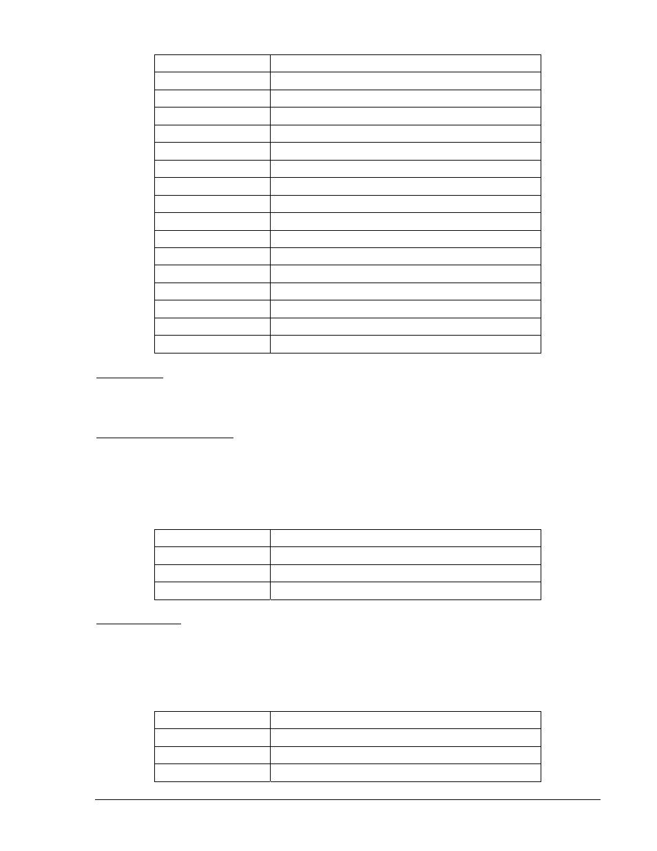
Table 6-9. Programmable Output Contact Terminals
Terminal Description
51 (COM 1, 2, 3)
Common connection for outputs 1, 2, and 3
52 (OUT 1)
Programmable output 1
53 (OUT 2)
Programmable output 2
54 (OUT 3)
Programmable output 3
55 (COM 4, 5, 6)
Common connection for outputs 4, 5, and 6
56 (OUT 4)
Programmable output 4
57 (OUT 5)
Programmable output 5
58 (OUT 6)
Programmable output 6
59 (COM 7, 8, 9)
Common connection for outputs 7, 8, and 9
60 (OUT 7)
Programmable output 7
61 (OUT 8)
Programmable output 8
62 (OUT 9)
Programmable output 9
63 (COM 10, 11, 12)
Common connection for outputs 10, 11, and 12
64 (OUT 10)
Programmable output 10
65 (OUT 11)
Programmable output 11
66 (OUT 12)
Programmable output 12
USB Interface
A mini-B USB socket enables local communication with a PC running BESTCOMSPlus software. The
DGC-2020 is connected to a PC using a standard USB cable equipped with a type A plug on one end
(PC termination) and a mini-B plug on the other end (DGC-2020 termination).
RS-485 Communication Port
DGC-2020 controllers with the optional RS-485 communication port (style number xxxRxxxxx) are
equipped for polled communication over a Modbus™ network. Twisted-pair, shielded cable is
recommended for RS-485 port connections. RS-485 communication port terminals are listed in Table
6-10.
Table 6-10. RS-485 Communication Port Terminals
Terminal Description
12 (485 SHIELD)
Shield connection for RS-485 cable
13 (485B)
RS-485 send/receive B connection
14 (485A)
RS-485 send/receive A connection
CANbus Interface
These terminals provide communication using the SAE J1939 protocol or the MTU protocol and provide
high-speed communication between the DGC-2020 and an MTU engine ECU on an electronically
controlled engine. Connections between the MTU engine ECU and DGC-2020 should be made with
twisted-pair, shielded cable. CANbus interface terminals are listed in Table 6-11. Refer to Figure 6-4 and
Figure 6-5.
Table 6-11. CANbus Interface Terminals
Terminal Description
48 (CAN L)
CAN low connection
49 (CAN H)
CAN high connection
50 (SHIELD)
CAN drain connection