Winco DGC-2020 User Manual
Page 177
Name Description
Symbol
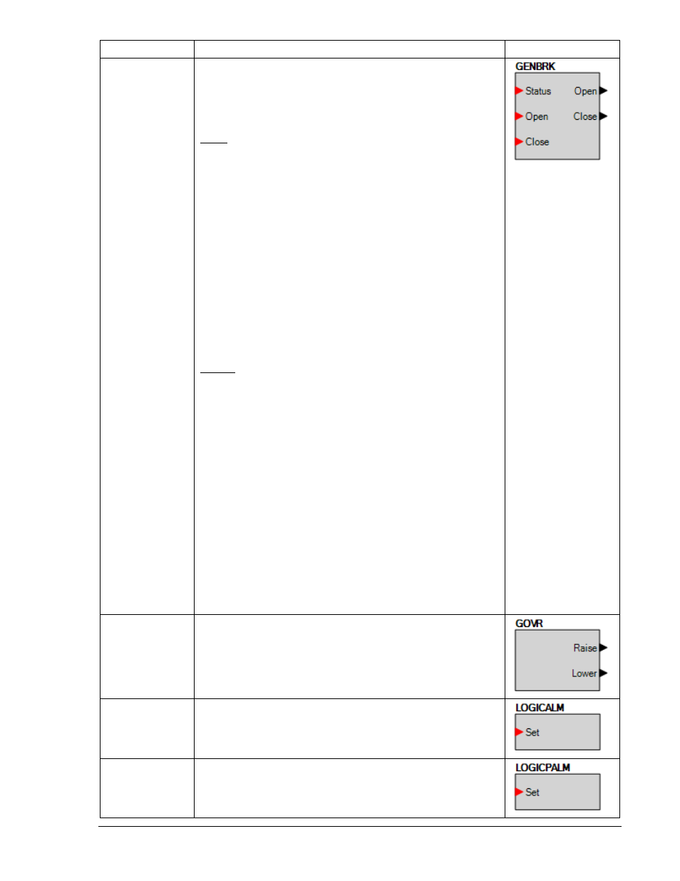
GENBRK
This element is used to connect the breaker open and close output
signals from the DGC-2020 to physical output contacts to open and
close the generator breaker, and map breaker status feedback to a
contact input. In addition, contact inputs can be mapped to allow
switches to be implemented to manually initiate breaker open and
close requests.
Inputs
Status: This input allows a contact input to be mapped that will
provide breaker status feedback to the DGC-2020. When the
contact input is closed, the breaker is indicated to be closed. When
the contact input is open, the breaker is indicated to be open.
Open: This input allows a contact input to be mapped that can be
used to initiate a manual breaker open request. When this input is
pulsed closed while the DGC-2020 is in RUN or AUTO mode, the
breaker will open.
Close: This input allows a contact input to be mapped that can be
used to initiate a manual breaker close request. When this input is
pulsed and the DGC-2020 is in AUTO or RUN mode, and the
generator is stable, a close request will be initiated. If the Dead Bus
Close Enable parameter is TRUE, and the bus is dead, the breaker
will close. If the bus is stable, the DGC-2020 will synchronize the
generator to the bus, and then close the breaker. If the
synchronizer option is not available, the DGC-2020 can still close
the breaker if some external means is employed to synchronize the
generator to the bus.
Outputs
The outputs must be mapped to the contact outputs of the DGC-
2020 that will be used to drive the breaker.
Open: This output is pulsed TRUE (closes the output contact it is
mapped to) when the DGC-2020 is providing a signal to the
breaker to open. It will be a pulse if the Breaker Output Contact
Type is set to Pulse on the Breaker Hardware screen under
Breaker Management in the Settings Explorer, and the length is
determined by the Open Pulse Time. It will be a constant output if
the Generator Breaker Hardware Contact Type is set to
continuous. Note the pulse time must be set long enough for the
breaker to actually open before the pulse is removed.
Close: This output is pulsed TRUE (closes the output contact it is
mapped to) when the DGC-2020 is providing a signal to the
breaker to close. It will be a pulse if the Breaker Output Contact
Type is set to Pulse on the Breaker Hardware screen under
Breaker Management in the Settings Explorer, and the length is
determined by the Open Pulse Time. It will be a constant output if
the Generator Breaker Hardware Contact Type is set to
continuous. Note the pulse time must be set long enough for the
breaker to actually open before the pulse is removed.
GOVR
Can be connected to inputs of other logic blocks. When the
Governor is being raised, the Raise output is TRUE. When being
lowered, the Lower output is TRUE.
LOGICALM
When this input is TRUE, the DGC-2020 goes into an Alarm
condition.
LOGICPALM
When this input is TRUE, the DGC-2020 goes into a Pre-alarm
condition.
9400200990 Rev K
DGC-2020 BESTlogic+ Programmable Logic
5-15