External rtd input connections, Canbus interface, External rtd input connections -6 – Winco DGC-2020 User Manual
Page 250: Canbus interface -6, Table 10-2. input and output terminals -6, Aem-2020
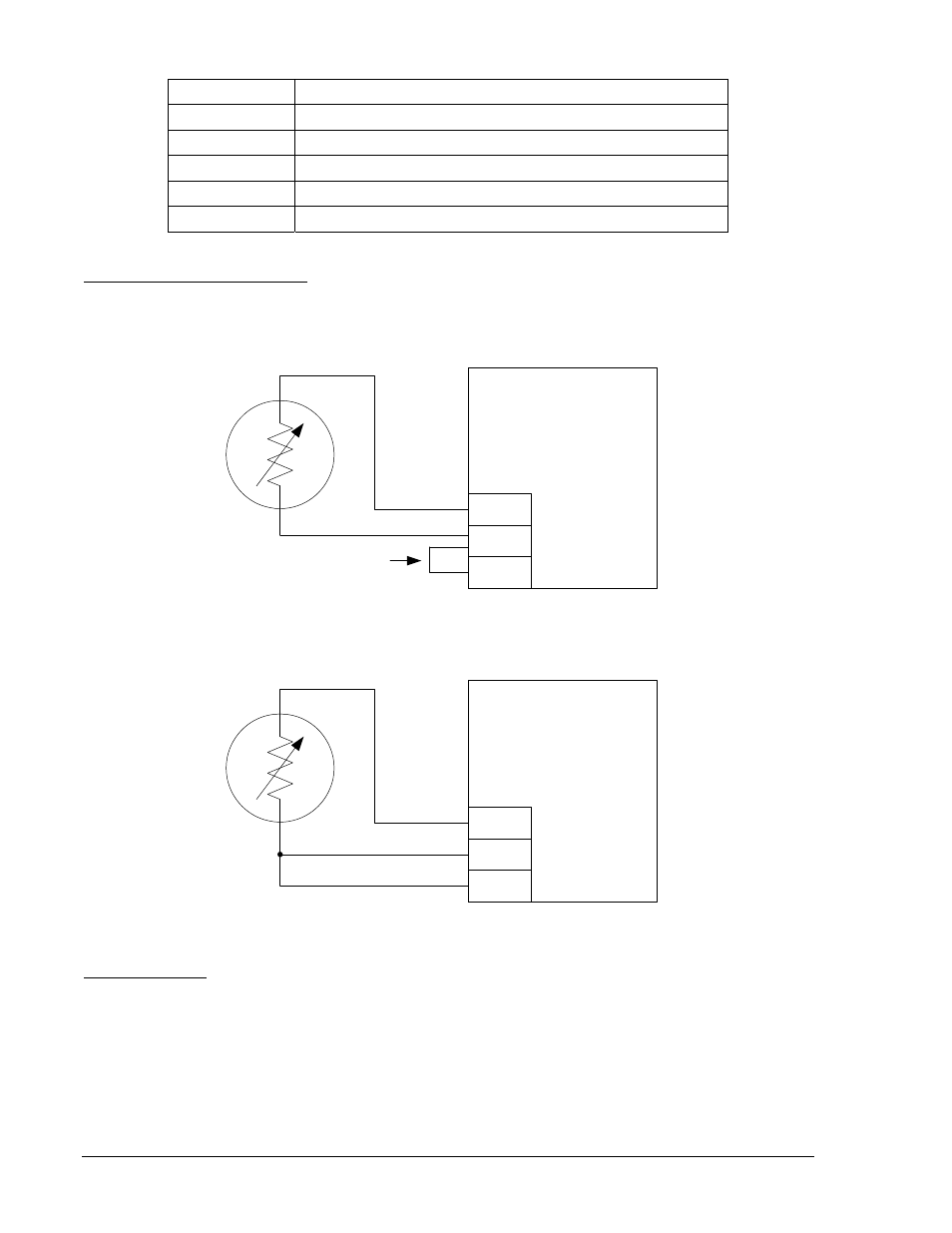
Table 10-2. Input and Output Terminals
Connector Description
P1
Operating Power and CANbus
P2
RTD Inputs 1 - 8
P3
Analog Inputs 1 - 8 and Analog Outputs 1 - 4
P4
Thermocouple 1 Input
P5
Thermocouple 2 Input
External RTD Input Connections
External 2-wire RTD input connections are shown in Figure 10-3. Figure 10-4 shows external 3-wire RTD
input connections.
RTD1+
RTD1–
RTD1C
AEM-2020
Jumper
P
00
5
3-
64
BLACK
RED
Figure 10-3. External Two-Wire RTD Input Connections
RTD1+
RTD1–
RTD1C
AEM-2020
P
00
5
3-
65
RED
BLACK
BLACK
Figure 10-4. External Three-Wire RTD Input Connections
CANbus Interface
These terminals provide communication using the SAE J1939 protocol and provide high-speed
communication between the Analog Expansion Module and the DGC-2020. Connections between the
AEM-2020 and DGC-2020 should be made with twisted-pair, shielded cable. CANbus interface terminals
are listed in Table 10-3. Refer to Figure 10-5 and Figure 10-6.
10-6
DGC-2020 AEM-2020 (Analog Expansion Module)
9400200990 Rev K