Operating power, Analog inputs, Analog outputs – Winco DGC-2020 User Manual
Page 228: Operating power -8, Analog inputs -8, Analog outputs -8, Table 8-1. operating power terminals -8, Table 8-2. analog input terminals -8, Table 8-3. analog output terminals -8
8-8
DGC-2020 LSM-2020 (Load Share Module)
9400200990 Rev K
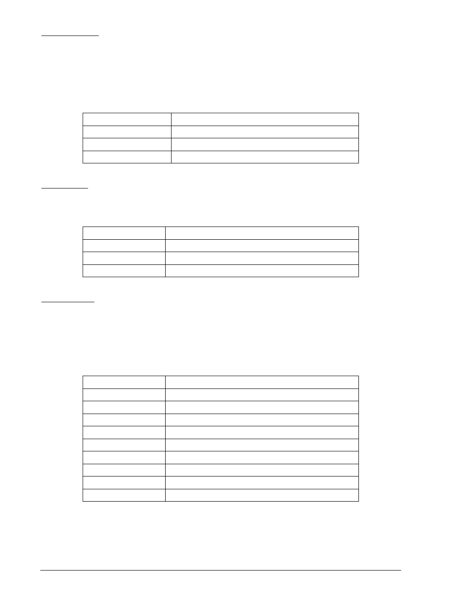
Operating Power
The LSM-2020 operating power input accepts either 12 Vdc or 24 Vdc and tolerates voltage over the
range of 6 to 32 Vdc. Operating power must be of the correct polarity. Although reverse polarity will not
cause damage, the LSM-2020 will not operate. Operating power terminals are listed in Table 8-1.
It is recommended that a fuse be added for additional protection for the wiring to the battery input of the
LSM-2020. A Bussmann ABC-7 fuse or equivalent is recommended.
Table 8-1. Operating Power Terminals
Terminal Description
P2-1 (CHASSIS)
Chassis ground connection
P2-2 (BATT+)
Positive side of operating power input
P2-3 (BATT–)
Negative side of operating power input
Analog Inputs
These inputs can be used for var, PF, or kW control. Analog input terminals are listed in Table 8-2.
Table 8-2. Analog Input Terminals
Terminal Description
P2-9 (V+)
Voltage input used for var, PF, or kW control.
P2-8 (IN–)
Common for voltage or current.
P2-7 (I+)
Current input used for var, PF, or kW control.
Analog Outputs
The LSM-2020 has three sets of analog output contacts: AVR control, GOV control, and Load Share Line.
The AVR control output contacts provide remote control of the generator voltage setpoint. The GOV
control output contacts provide remote control of the generator speed (RPM) setpoint. The generator
uses the measured LS (Load Share Line) output to calculate the per unitized average load level, and
uses that as the set point for its kW controller. Analog input terminals are listed in Table 8-3.
Table 8-3. Analog Output Terminals
Terminal Description
P2-18 (AVR+)
AVR control output positive
P2-17 (AVR–)
AVR control output negative
P2-16 (AVR’)
Provides additional landing point for external resistor
P2-15 (GOV+)
GOV control output positive
P2-14 (GOV–)
GOV control output negative
P2-13 (GOV’)
Provides additional landing point for external resistor
P2-6 (LS+)
Load share line positive
P2-5 (LS–)
Load share line negative
P2-4 (LS’)
Provides additional landing point for external resistor