Elements, Elements -11 – Winco DGC-2020 User Manual
Page 173
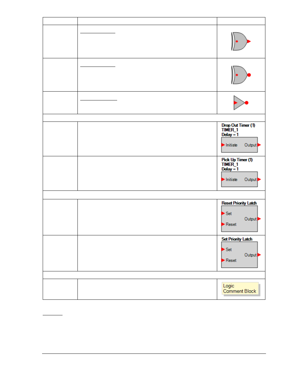
Name Description
Symbol
XOR
Input Output
0 0
0
0 1
1
1 0
1
1 1
0
XNOR
Input Output
0 0
1
0 1
0
1 0
0
1 1
1
NOT
(INVERTER)
Input Output
0 1
1 0
Pickup and Dropout Timers
Drop Out Timer
Used to set a delay in the logic.
Pickup Up
Timer
Used to set a delay in the logic.
Latches
Reset Priority
Latch
A positive going edge on the Set input sets the latch, as long as the
Reset input is false. A positive edge on the Reset input will clear the
latch.
Set Priority
Latch
A positive going edge on the Set input sets the latch. A positive going
edge on the Reset input will clear the latch, as long as the Set input is
false.
Other
Comment
Block
Enter user comments.
Elements
This group contains elements for the 51, 27, 47, 59, 81, 32, and 40. It also contains elements for
Generator Breaker, AVR Raise/Lower, Governor Raise/Lower, Logic Alarm, Logic Pre-Alarm, Modem,
Configurable Elements, AUTO Mode, OFF Mode, RUN Mode, Parallel to Mains, and Run with Load.
Table 5-3 lists the names and descriptions of the elements in the Elements group.
9400200990 Rev K
DGC-2020 BESTlogic+ Programmable Logic
5-11