Figure 4-52. avr bias control settings -57 – Winco DGC-2020 User Manual
Page 127
droop is also the mode when the generator breaker is closed if kW load sharing is disabled. If it is desired
to disable voltage droop, set the droop percentage to 0. The voltage droop gain setting
Z
determines the
gain factor applied to the voltage droop percentage to compensate for governor differences and achieve
desired droop performance. In order to test the operation of droop, the unit must be loaded to full load
and the resulting generator voltage should be compared to the desired droop. If it is not possible to load
the unit to full load, the droop test may be performed at partial load. The expected voltage is determined
by the following equation.
Expected voltage reduction in droop - (actual load/machine capacity)
(droop percentage/100) rated
voltage.
If the actual voltage drop does not match the expected value, calculate the error by dividing the expected
drop by the actual drop, and putting the result in as the droop gain.
Ramp rate
AA
is defined as the rate, in percentage of machine capacity, at which the machine will ramp up
its Var/PF when loading or coming online. The machine also uses this rate to unload prior to cooling
down. If a machine is the only machine online, ramping will not be in effect.
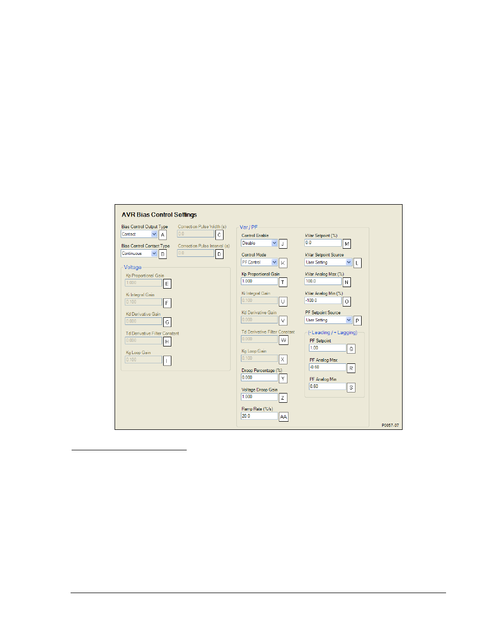
BESTCOMSPlus AVR bias control settings (DGC-2020, Bias Control Settings, AVR Bias Control
Settings) are illustrated in Figure 4-52.
Figure 4-52. AVR Bias Control Settings
A
Bias Control Output Type: Contact or Analog.
B
Bias Control Contact Type: Continuous or Proportional.
C
Correction Pulse Width: Adjustable from 0 to 99.9 s in 0.1 s increments.
D
Correction Pulse Interval: Adjustable from 0 to 99.9 s in 0.1 s increments.
E
Proportional Gain (Kp): Adjustable from 0 to 1,000 in increments of 0.001.
F
Integral Gain (Ki): Adjustable from 0 to 1,000 in increments of 0.001.
G
Derivative Gain (Kd):
Adjustable from 0 to 1,000 in increments of 0.001.
H
Derivative Filter Constant (Td):
Adjustable from 0 to 1 in increments of 0.001.
I
Loop Gain (Kg): Adjustable from 0 to 1,000 in increments of 0.001.
J
Control: Disable or Enable.
K
Control Mode: Var Control or PF Control.
L
kVar Setpoint Source: User Setting, LSM Analog Input 1, or Analog Inputs 1-8.
M
kVar Setpoint: Adjustable from -100 to 100 percent in 0.1 % increments.
N
kVar Analog Max: Adjustable from 0 to 100 percent in 0.1 % increments.
O
kVar Analog Min: Adjustable from 0 to 100 percent in 0.1 % increments.
9400200990 Rev K
DGC-2020 BESTCOMSPlus Software
4-57