14 i/o monitoring function, 14 i/o monitoring function -50, I/o monitoring function -50 – KEYENCE SL-V Series User Manual
Page 74: I/o monitoring function, How to use the i/o monitoring function, Input
2-50
2
SL-V-M-NO2-E
2-14
I/O Monitoring Function
The I/O monitoring function is a NON-SAFETY-RELATED function.
This function simply informs the user of the state of several I/Os on the SL-V through the indicators of the SL-V.
Connection with a PLC or other input device can be verified, as the non safety-related outputs (i.e.
except for OSSD) can be activated through the I/O monitoring function.
The OSSD keeps an OFF state while the I/O monitoring function is activated.
How to use the I/O monitoring function
1. Turn OFF the power to the SL-V.
2. With the interlock mode selection input (pink wire on the transmitter) open (completely disconnected),
turn ON the power. The SL-V will activate the I/O monitoring function.
When the I/O monitoring function is activated, all the center indicators turn OFF. Bar LED No. 1 on the
transmitter lights red. On the receiver, bar LED No. 1 lights red when using the NPN output type cable,
and bar LED No. 2 lights red when using the PNP output type cable.
3. To deactivate the I/O monitoring function, turn OFF the power, then connect the interlock mode selec-
tion input to a +24 V or 0 V source. Turn ON the power to complete the deactivation.
See "Interlock Function" (page 2-7)
• The I/O monitoring function cannot be used if the interlock is configured through the SL-V1HS. (The I/O
monitoring function is not activated even if the interlock selection input is kept open circuit.)
• The interlock mode selection input must be open (completely disconnected) while the I/O monitoring
function is activated.
If this input is connected to +24 V or 0 V, the bar LED indicators and the function indicators will show
irregular operation.
Input
You can check the state of the signal input and output in the following table:
When the following input turns ON, the center indicators also turn ON.
(1) Muting input 1 (all center indicator light green)
(2) Muting input 2 (all center indicator light red)
(3) Override input (only top of center indicator light red, the others are OFF)
(4) Wait input (only bottom of center indicator light red, the others are OFF)
When inputs (1) to (4) turn ON at the same time, the input with higher priority is indicated.
The order of priority is: (4) > (3) > (2) > (1)
NOTE
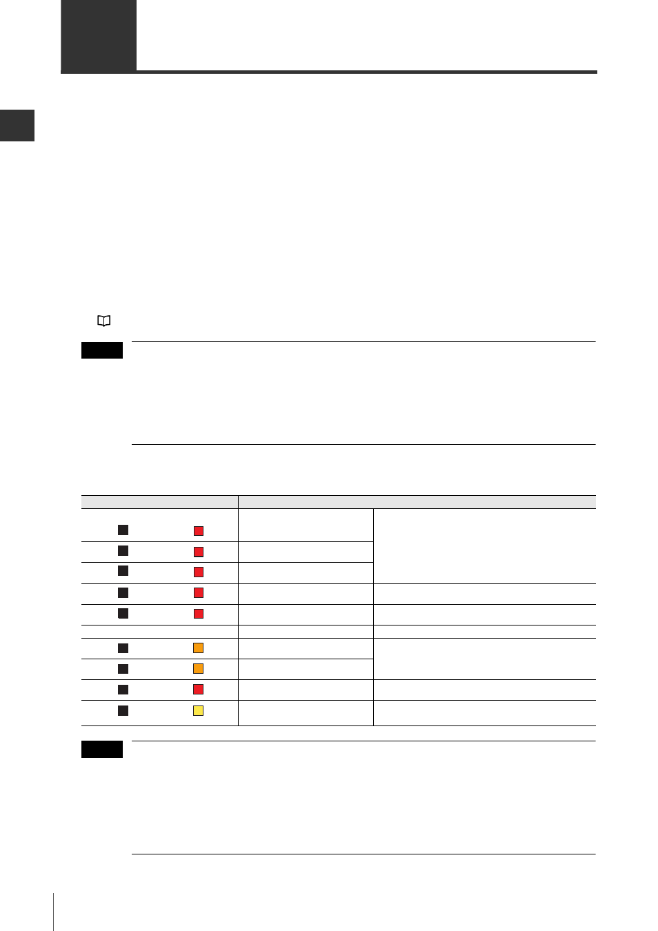
Indicators (on receiver)
Description
Reset input
Blinking red
: Input ON
Light OFF
: Input OFF
Wait input
EDM input
Using PNP output type cable
Red light
: Using PNP output type cable
Using NPN output type cable
Red light
: Using NPN output type cable
Muting input 1
Blinking orange
: Input ON
Light OFF
: Input OFF
Muting input 2
Always red
–
Override input
Blinking yellow
: Input ON
Light OFF
: Input OFF
5
5
4
4
3
3
2
2
1
1
MUTE1
MUTE1
MUTE2
MUTE2
OSSD
OSSD
INTER
LOCK
INTER
LOCK
NOTE