Wiring, Conditions for initiation of override – KEYENCE SL-V Series User Manual
Page 70
2-11
Temporary Suspension of Safety Function
2-46
2
SL-V-M-NO2-E
•
Those who use the override function must fulfill all requirements related to the override function.
KEYENCE accepts NO responsibility or NO liability for any damage or any injury due to the
unauthorized installation, usage, or maintenance, which are not specified in this user’s manual,
and/or due to noncompliance with the laws, rules, regulations and standards in the country or
region in which the SL-V is used.
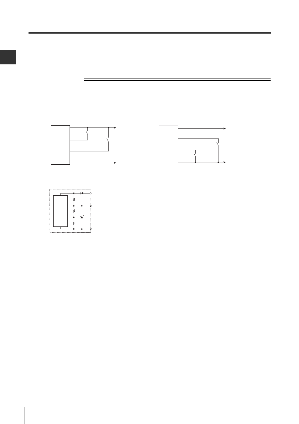
Wiring
The input circuit for reset input and override input is as follows.
Conditions for initiation of override
The override condition is initiated if all of the following conditions are met and the reset input goes to ON
state within 0.04 to 1 s after override input turns ON.
• The SL-V is not in a lockout condition.
• OSSD is in the OFF state (including interlock condition).
• SL-V detects interruption in the detection zone. (One or more beam axis is blocked.)
• Either of muting inputs, or both, turns ON state.
Brown
Blue
+24 V
0 V
Yellow
Red/Black
(Override input)
(Reset input)
Short-circuit current: 2.5mA
Receiver
Input circuit
diagram
Yellow
Brown
Blue
0 V
+24 V
Red/Black
(Override input)
(Reset input)
Receiver
Input circuit
diagram
Short-circuit current: 2.5mA
When using a PNP output type cable
When using an NPN output type cable
Brown
Light blue,
Light blue/Black
Blue
Receiver
Main
circuit