Normal mode (default), Summary, Wiring – KEYENCE SL-V Series User Manual
Page 43
2-8
State Information Output
2-19
2
SL-V-M-NO2-E
Normal mode (default)
Summary
When the power turns on, the pulse output (number of pulses on state information output 2 while state information output 1
is ON) indicates that the SL-V is in normal operation. After that, if the SL-V changes to one of the states shown below ("SL-
V state" column), the pulse output generates the corresponding number of pulses one time to indicate the state of the SL-V.
• If the SL-V goes into a lockout condition immediately after the power is turned on, the SL-V may not output
the pulses indicating the lockout condition but instead output the pulses indicating the normal operation.
• The SL-V can only output the state information pulses when the communication cable is connected cor-
rectly upon power-up.
See "Examples of Wiring" (page 4-5)
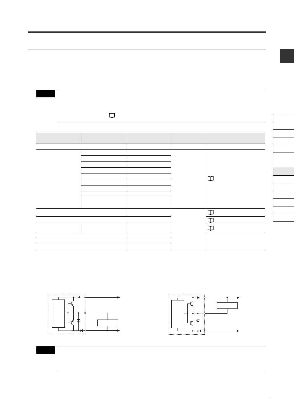
Wiring
The grey (state information output 1), grey/black (state information output 2), and red (AUX) wires must
be connected individually to the device inputs.
Use the AUX output here because the OSSD is used as a safety output.
Output rating : 26.4 V DC or less, 50 mA or less
Regardless of using an NPN or a PNP output type cable, the SL-V state information output can be con-
nected to PNP and NPN devices. Refer to the time charts mentioned in this manual because the logic is
different depending on the connected device.
SL-V state
Detail information for
each error
The number of pulses
OSSD state
Refer to page
Normal operation (state other than shown below)
1
ON or OFF
–
Lockout condition
OSSD error
2
OFF
See "Troubleshooting" (page A-2)
EDM error
3
Communication error
4
Receiver error
5
Transmitter error
6
Muting lamp error
7
Interlock error
8
System error
9
Software configuration
error
10
Muted condition
2
ON
See "Muting function" (page 2-29)
Override condition
3
See "Override function" (page 2-45)
Muted or override condition Muting lamp error
4
See "Muting function" (page 2-29)
Muted condition (bank 1 selected)
5
–
Muted condition (bank 2 selected)
6
Muted condition (bank 3 selected)
7
NOTE
Grey, Grey/Black, Red
Input device
Brown
Blue
Transmitter
Main
circuit
0V
+24V
Grey. Grey/Black, Red
Input device
Brown
Blue
Transmitter
Main
circuit
0V
+24V
For connecting a PNP input device
For connecting an NPN input device
NOTE
Cable
Self-diagnosis
Series Connection
Interlock
AUX
EDM
Wait
State Information
Alert
Clear/Blocked
Suspension
Fixed
Reduced
Monitoring