Simple mode, Wiring, Time chart – KEYENCE SL-V Series User Manual
Page 47
2-8
State Information Output
2-23
2
SL-V-M-NO2-E
Simple mode
State information output 1 indicates a lockout condition. State information output 2 indicates a muted
condition.
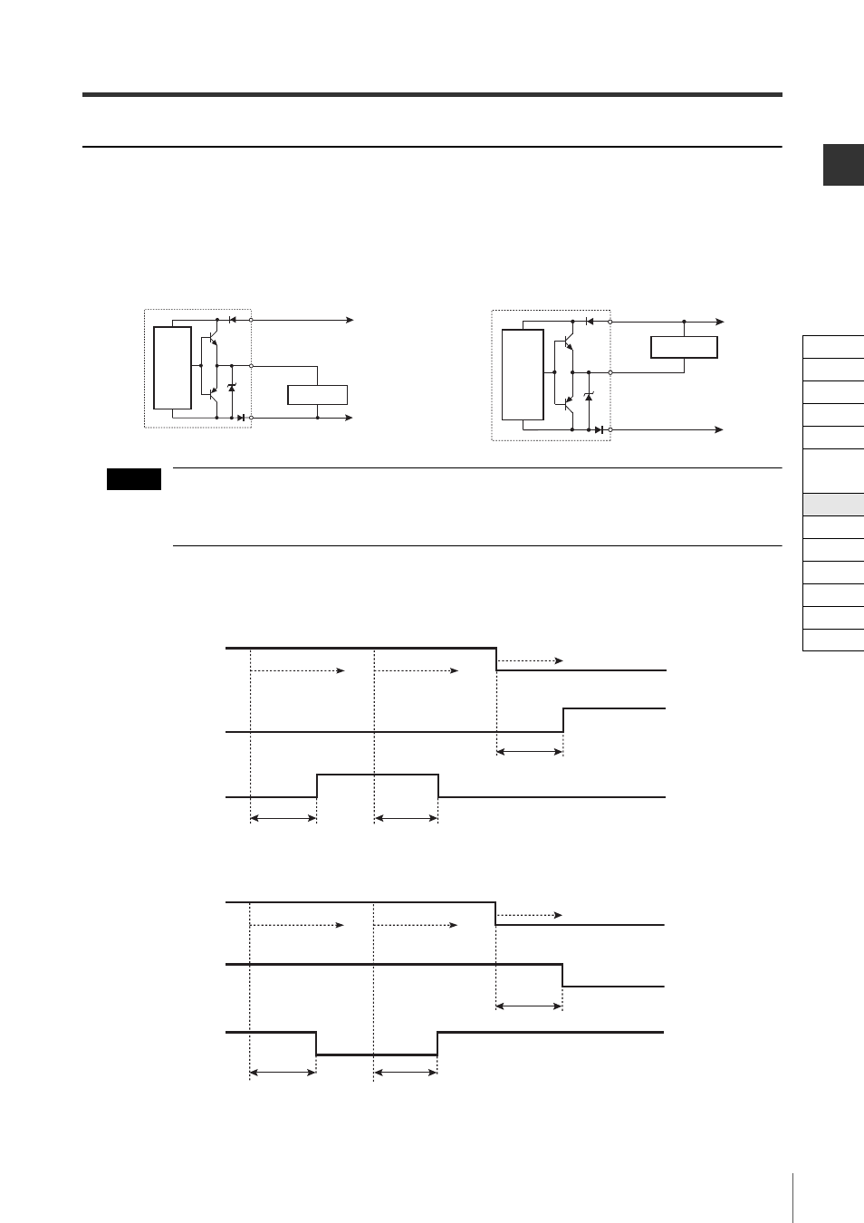
Wiring
The grey (state information output 1) and grey/black (state information output 2) wires must be con-
nected individually to the device inputs.
Regardless of using an NPN or a PNP output type cable, the SL-V state information output can be con-
nected to PNP and NPN devices. Refer to the time charts mentioned in this manual because the logic is
different depending on the connected device.
Time chart
• When using a PNP output type cable to connect to a PNP input device
• When using an NPN output type cable to connect to an NPN input device
• When using a PNP output type cable to connect to an NPN input device
• When using an NPN output type cable to connect to a PNP input device
Grey, Grey/Black
Input device
Brown
Blue
0V
+24V
Transmitter
Main
circuit
Grey, Grey/Black
Input device
Brown
Blue
0V
+24V
Transmitter
Main
circuit
For connecting a PNP input device
For connecting an NPN input device
NOTE
SL-V goes to lockout condition
Muted or override condition
Not muted or override condition
Within 120 ms
Within 120 ms
Within 120 ms
State information
output 1
State information
output 2
ON
OFF
ON
OFF
ON
OFF
OSSD
SL-V goes to lockout condition
Muted or override condition
Not muted or override condition
Within 120 ms
Within 120 ms
Within 120 ms
State information
output 1
State information
output 2
ON
OFF
ON
OFF
ON
OFF
OSSD
Cable
Self-diagnosis
Series Connection
Interlock
AUX
EDM
Wait
State Information
Alert
Clear/Blocked
Suspension
Fixed
Reduced
Monitoring