Cable color and pin assignment, Cable color and pin assignment -3, Simple function type – KEYENCE SL-V Series User Manual
Page 27: Multi-function type
2-1
Cable Selection and Function
2-3
2
SL-V-M-NO2-E
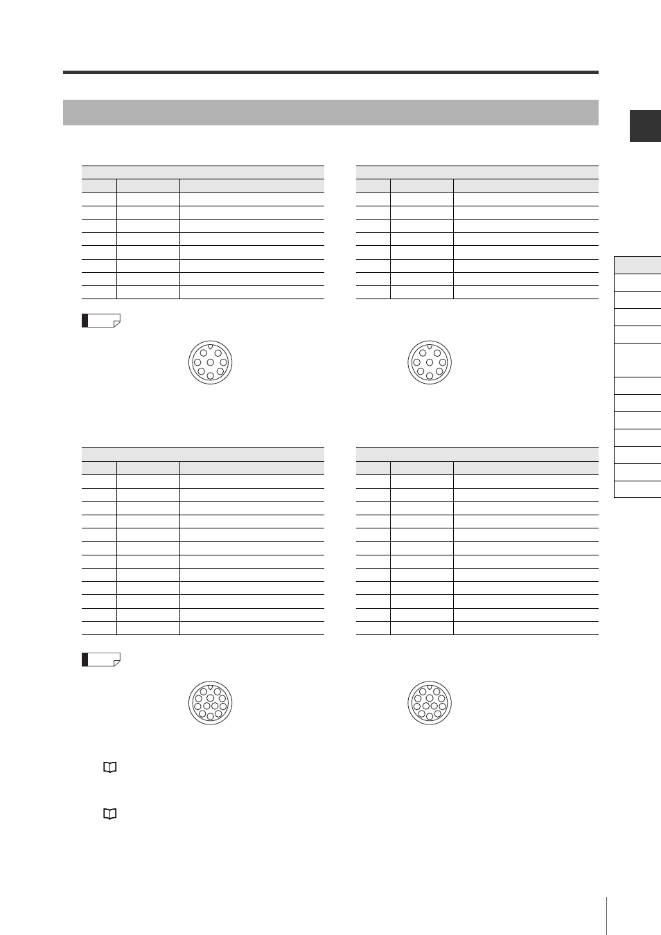
Simple function type
M12 connector male pin assignment
M12 connector female pin assignment
Multi-function type
M14 connector male pin assignment
M14 connector female pin assignment
*1 The following changes apply when the muting bank function is enabled.
Pink: Muting bank input 3, Violet: Muting bank input 1, Red/black: Muting bank input 2
*2 If the center indicator is set to the Built-in indicator mode, this is used for the control input of the indi-
cation state.
Cable color and pin assignment
Transmitter
Receiver
Pin No.
Wire color
Assigned function
Pin No.
Wire color
Assigned function
1
Pink
Interlock mode selection input
1
White
OSSD 2
2
Brown
+24 V
2
Brown
+24 V
3
Violet
Wait input
3
Black
OSSD 1
4
Green
Interlock-reset-ready output
4
Yellow
RESET input
5
Orange
Communication cable 1 (RS485_+)
5
Orange
Communication cable 1 (RS485_+)
6
Orange/Black Communication cable 2 (RS485_-)
6
Orange/Black Communication cable 2 (RS485_-)
7
Blue
0 V
7
Blue
0 V
8
Red
AUX (auxiliary) output
8
Red
EDM input
Reference
5
8
7
3
4
2
1
6
5
8
3
7
6
1
2
4
Transmitter
Receiver
Pin No.
Wire color
Assigned function
Pin No.
Wire color
Assigned function
1
Pink
Interlock mode selection input*
1
1
White
OSSD 2
2
Brown
+24 V
2
Brown
+24 V
3
Violet
Wait input*
1
*
2
3
Black
OSSD 1
4
Green
Interlock-reset-ready output
4
Yellow
RESET input
5
Orange
Communication cable 1 (RS485_+)
5
Orange
Communication cable 1 (RS485_+)
6
Orange/Black Communication cable 2 (RS485_-)
6
Orange/Black Communication cable 2 (RS485_-)
7
Blue
0 V
7
Blue
0 V
8
Red
AUX (auxiliary) output
8
Red
EDM input
9
Grey
State information output 1
9
Red/Black
Override input*
1
*
2
10
Grey/Black
State information output 2
10
Yellow/Black
Muting lamp output
11
Pink/Black
Alert output
11
Light blue
Muting input 1
12
White/Black
Clear/Blocked Output
12
Light blue/Black Muting input 2
Reference
6
10
12 11
3
4
5
2
1
9
8
7
6
10
11 12
9
8
7
1
2
3
4
5
Cable
Self-diagnosis
Series Connection
Interlock
AUX
EDM
Wait
State Information
Alert
Clear/Blocked
Suspension
Fixed
Reduced
Monitoring