Wiring the muting inputs, Time chart – KEYENCE SL-V Series User Manual
Page 104
3-8
System Configuration for the Muting Function
3-28
In
3
SL-V-M-NO3-E
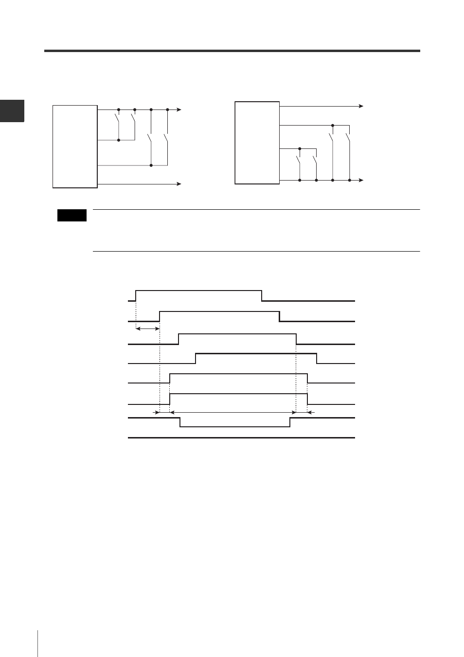
Wiring the muting inputs
Output of the switch or sensor used as the muting device must be the same as the cable used.
Example: PNP output if PNP cable is used, or NPN output if NPN cable is used.
Also, the muting device must be able to handle a 3 mA current load.
Time chart
+24 V
0V
Brown
Blue
Light blue
Sensor
A1
Sensor
B1
Sensor
A2
Sensor
B2
Light blue/black
(Muting input 2)
(Muting input 1)
Receiver
Short-circuit current: 2.5 mA
Sensor
A1
Sensor
A2
Sensor
B1
Sensor
B2
0 V
+24V
Receiver
Light blue
Brown
Blue
Light blue
/black
(Muting input 1)
(Muting input 2)
Short-circuit current: 2.5 mA
When using the PNP output cable
When using the NPN output cable
NOTE
Sensor A2
ON
OFF
Muted condition
Not muted condition
ON
OFF
Sensor A1
Sensor B2
ON
Light ON
OFF
ON
OFF
Sensor B1
SL-V
No
interruption
Interruption
OSSD
ON
OFF
Light OFF
Muting lamp
Within 0.04 to 3 s
Within approx. 5 min.
20 ms max.
20 ms max.