6 external device monitoring (edm function), External device monitoring (edm function) -15, External device monitoring (edm function) – KEYENCE SL-V Series User Manual
Page 39: Wiring, Wiring when not using the edm function, Time chart
2-15
2
SL-V-M-NO2-E
2-6
External Device Monitoring (EDM Function)
EDM (External Device Monitoring) is a function of the SL-V that monitors the state of control devices which
are externally connected to the SL-V. The SL-V can detect a fault such as welded contacts on external
devices if the EDM function is activated.
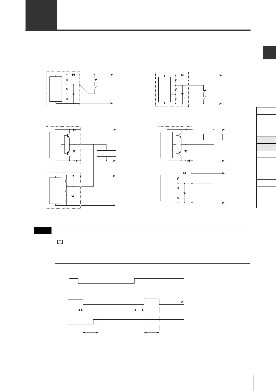
Wiring
Wiring when not using the EDM function
* When the EDM is not applied thorough the SL-VH1S, the EDM input should not be connected to the
AUX output (keep open-circuit).
If the AUX output is not connected to any other devices, the red wires on the transmitter and receiver
should be short-circuited.
See "AUX (Auxiliary) Output" (page 2-14).
When short-circuiting the AUX output with the EDM input, the wait input should be turned to an ON state
once per second. If the wait input is turned on several times per second, the SL-V may go into a lockout
condition due to an EDM error.
Time chart
* This can be changed through the SL-VH1S. Refer to the "SL-VH1S User’s Manual" for more details.
(1) If the SL-V detects the operation of external device within the specified period of time (0.3 s) after the oper-
ation of OSSD (ON to OFF, or OFF to ON), the SL-V continues normal operation.
(2) Unless the SL-V detects the operation of an external device within the specified period of time (0.3 s) after
the operation of OSSD (ON to OFF, OFF to ON), the SL-V goes into a lockout condition due to an EDM error.
0V
+24V
Red
Brown
Short-circuit current: 10mA
Device 1
Device 2
Blue
Receiver
Main
circuit
0V
+24V
Red
Brown
Short-circuit current: 10mA
Device 1
Device 2
Blue
Receiver
Main
circuit
When using a PNP output type cable
When using an NPN output type cable
0V
+24V
Red (EDM input)*
Brown
Blue
Receiver
Main
circuit
Input device
Brown
Red (AUX output)
Blue
Transmitter
Main
circuit
0V
+24V
Red (AUX output)
Input device
Brown
Blue
Transmitter
Main
circuit
0V
+24V
0V
+24V
Red (EDM input)*
Brown
Blue
Receiver
Main
circuit
When using a PNP output type cable
When using an NPN output type cable
NOTE
Lockout condition
Specified
period of time*
Specified
period of time*
0.3 s
0.3 s
SL-V
ON
OFF
OSSD
ON
OFF
External device
(B contact)
Response time (ON to OFF)
Response time (ON to OFF)
(1)
(2)
No
interruption
Interruption
Cable
Self-diagnosis
Series Connection
Interlock
AUX
EDM
Wait
State Information
Alert
Clear/Blocked
Suspension
Fixed
Reduced
Monitoring