Examples of wiring – KEYENCE SL-V Series User Manual
Page 115
4-4
Examples of Wiring
4-7
Wirin
4
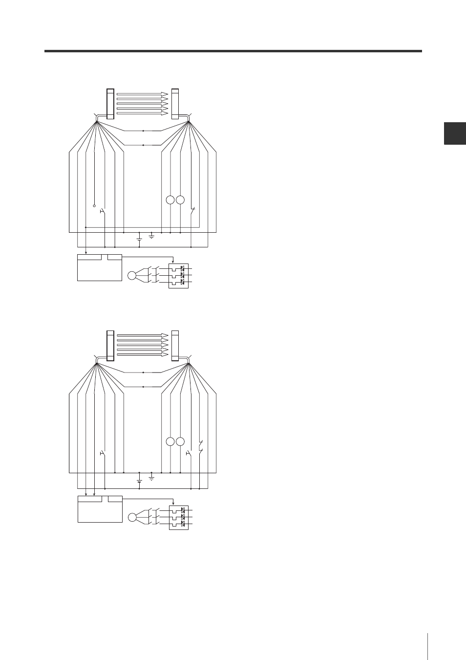
SL-V-M-NO4-E
Automatic reset mode
When not using the EDM function
Manual reset mode
K1, K2 : External device (Safety relay unit, etc.)
K3
: Solid state contactor
*1
S1
: The switch for wait input (N.O.)
*1
The violet wire needs to be capped it is not used.
(Open circuit : completely disconnected)
S2
: The switch for releasing lockout condition (N.C.)
The yellow wire must be short-circuited to 0 V if this
function is not used.
M
: 3-phase motor
PLC
: For the monitoring use
*1
*1
These are NON SAFETY-RELATED system.
K3
K2
K1
M
IN
OUT
PLC
S1
S2
Cable insulation: Black
Cable insulation: Grey
Transmitter
Receiv
er
(Inter
loc
k-reset-ready output) Green
(+24 V)
Bro
wn
(+24 V)
Bro
wn
(OSSD2) White
(OSSD1) Blac
k
(Reset input)
Y
ello
w
(EDM input) Red
(W
ait input)
Violet
(A
UX output) Red
(0 V)
Blue
(0 V)
Blue
Shield
Shield
K2
K1
(Inter
loc
k mode selection input) Pink
Orange/black
(Communication cable 2)
Orange
(Communication cable 1)
S1
S2
K1
K2
K3
K2
K1
M
IN
OUT
PLC
Cable insulation: Black
Cable insulation: Grey
Transmitter
Receiv
er
(Inter
loc
k-reset-ready output) Green
(+24 V)
Bro
wn
(+24 V)
Bro
wn
(OSSD2) White
(OSSD1) Blac
k
(Reset input)
Y
ello
w
(EDM input) Red
(W
ait input)
Violet
(A
UX output) Red
(0 V)
Blue
(0 V)
Blue
Shield
Shield
K2
K1
(Inter
loc
k mode selection input) Pink
Orange/black
(Communication cable 2)
Orange
(Communication cable 1)
K1, K2 : External device (Safety relay, magnet contactor,
etc.)
K3
: Solid state contactor
*1
S1
: The switch for wait input (N.O.)
*1
The violet wire needs to be capped it is not used.
(Open circuit : completely disconnected)
S2
: The switch for reset input (N.O.)
M
: 3-phase motor
PLC
: For the monitoring use
*1
*1
These are NON SAFETY-RELATED system.