10 clear/blocked output, 10 clear/blocked output -27, Clear/blocked output -27 – KEYENCE SL-V Series User Manual
Page 51: Clear/blocked output, Danger, Wiring, Conditions when the clear state is detected, Conditions when the blocked state is detected
2-27
2
SL-V-M-NO2-E
2-10
Clear/Blocked Output
The Clear/Blocked output is a NON-SAFETY-RELATED function.
This output simply informs the external devices (non safety-related devices) whether the beam axes are
clear or blocked. (“Clear” means no interruptions in the detection zone, “Blocked” means there is an
interruption in the detection zone.) This output is NOT synchronized with the OSSD operation. For exam-
ple, when the SL-V is in an interlock condition, the OSSD will turn OFF while the clear/blocked output
indicates “clear”. Another example is if the SL-V is muted or in override mode, the OSSD is ON but the
clear/blocked output may indicate “blocked”.
The Clear/Blocked Output is not allowed to be used as a safety output for any safety-related
control systems. This output should never constitute a part of a safety-related control system.
Using this function as a safety output may result in significant harm to machine operators
including serious injury or death.
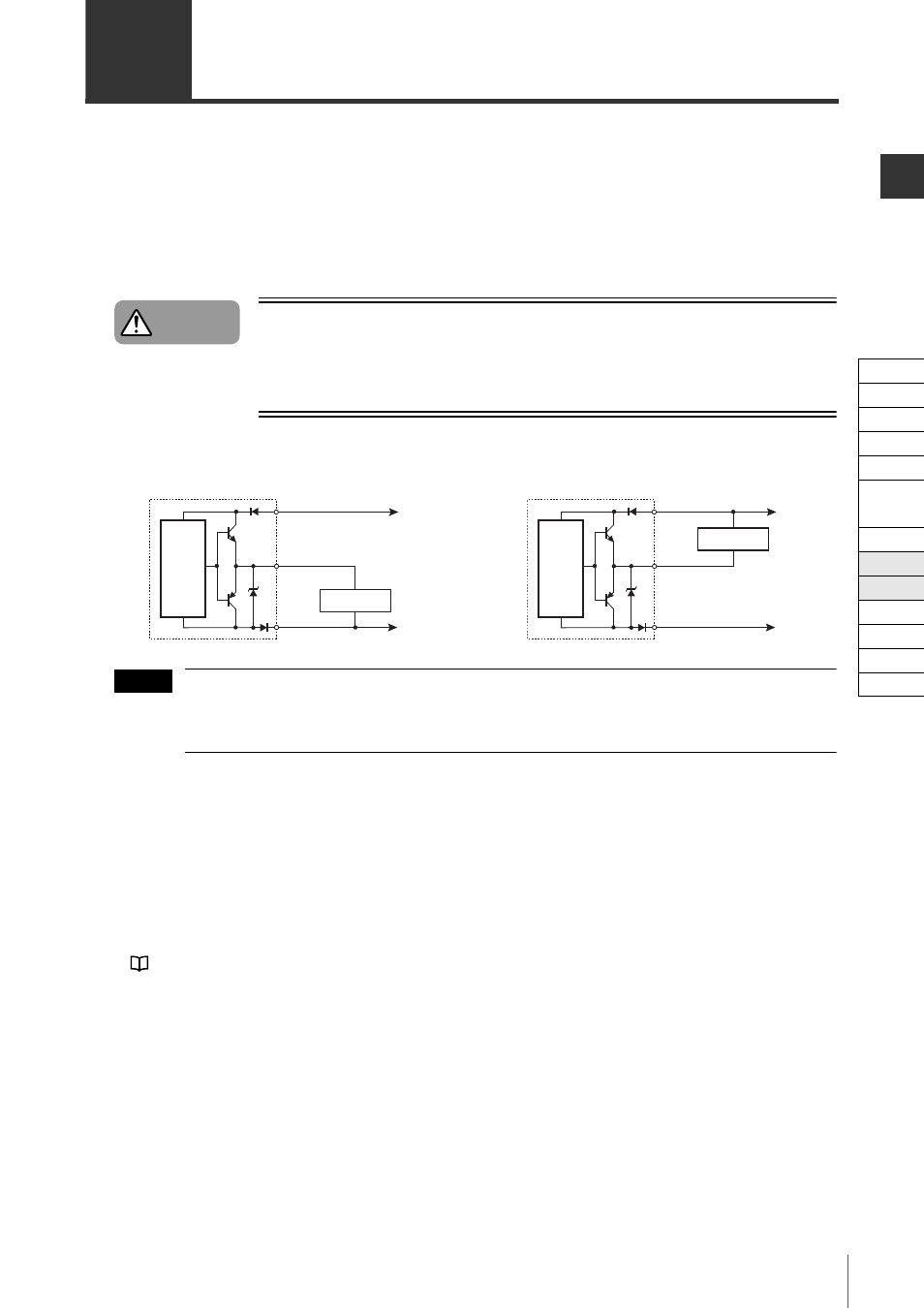
Wiring
Regardless of using an NPN or a PNP cable, the SL-V clear/blocked output can be connected to PNP and
NPN devices. Refer to the time charts mentioned in this manual because the logic is different depending
on the connected device.
Conditions when the clear state is detected
The Clear/Blocked output will turn ON when all beam axes are receiving 100% of the light.
Conditions when the blocked state is detected
The Clear/Blocked Output will be deactivated if any of the below three conditions is met.
• When at least one beam axis is blocked so that less than 100% of the light is received
• When the SL-V is in a lockout condition
• When the wait input is ON for the SL-VHS
See "Wait Input Function" (page 2-16)
The output is turned off if one of the above three conditions is fulfilled.
Danger
White/Black
Brown
Blue
0V
+24V
Receiver
Main
circuit
Input device
White/Black
Brown
Blue
0V
+24V
Receiver
Main
circuit
Input device
For connecting a PNP input device
For connecting an NPN input device
NOTE
Cable
Self-diagnosis
Series Connection
Interlock
AUX
EDM
Wait
State Information
Alert
Clear/Blocked
Suspension
Fixed
Reduced
Monitoring