Weld head motor control cable, Welding gas connections – Arc Machines 307 User Manual
Page 39
Arc Machines, Inc. Model 307 Orbital Tube Welder Training
Document No. 740096
Chapter 4. Page 5.
Rev.A
Weld Head Motor Control Cable
Remove dust cap on cable and insert weld head CONTROL connec-
tor into the Model 307 WELD HEAD connector identified by the
weld head symbol. Note positioning keyway. Hand tighten con-
necting ring after pins are seated. Do not force. (See figure on page 4.)
Welding Gas Connections
Gas Hoses. The gas hoses supplied with the Model 307 are selected for
suitability for high-purity orbital welding. Plastic materials which may be
used for high-purity welding differ with respect to permeability to mois-
ture and oxygen and resistance to heat and to particulation. None are
perfect. Gas hoses made from rubber or nylon are not suitable. Do not
use hoses that are longer than necessary.
CAUTION: The Model 307 arc gas solenoid valve is rated at 50 psi
(345KPa) maximum pressure, DO NOT EXCEED THIS RATING.
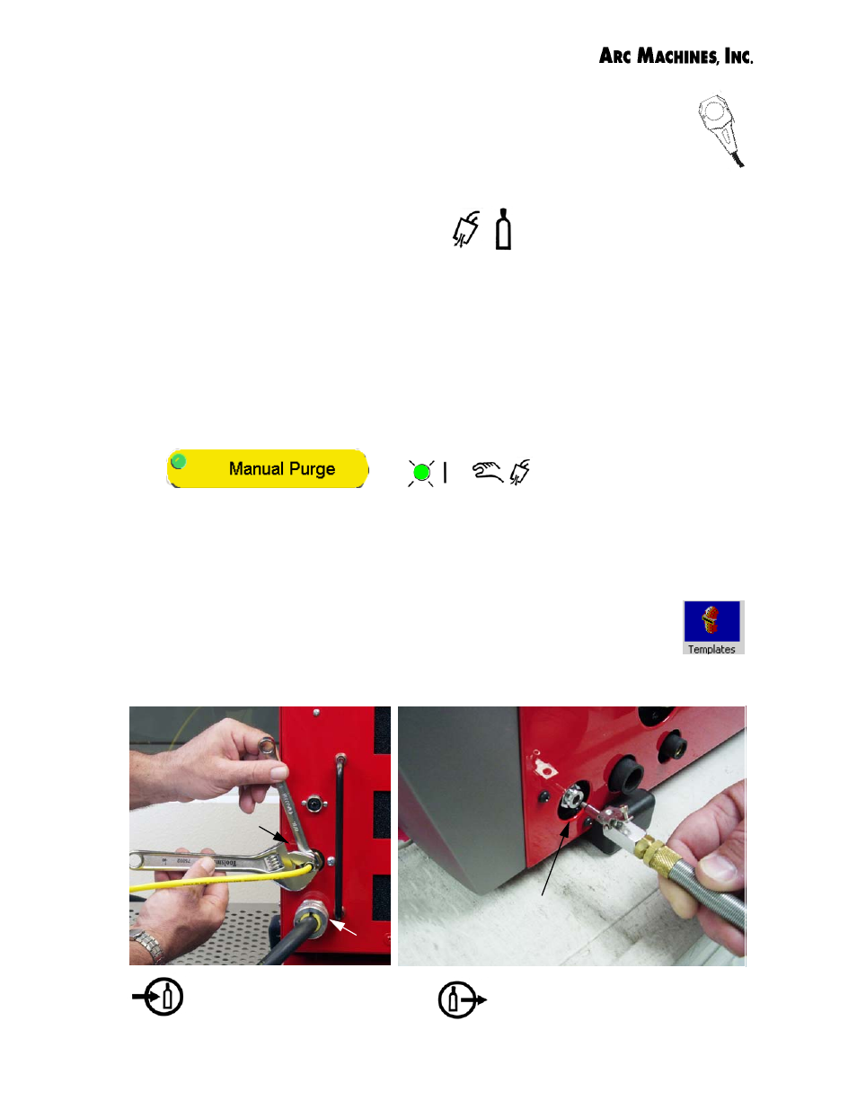
Use the Manual Purge button on the Model 307 Weld Schedule-Weld
Screen to set gas flow rate for the weld head. The Manual Purge must
be On with the gas input and gas output hoses plugged in for gas to flow.
Adjust flow rate to weld head from flowmeter on gas source.
Touch the Templates icon for factory recommended flow rates
for the weld head used in a particular weld schedule.
The ID purge must be supplied directly from the flow-meter/
regulator on the argon source.
Arc gas output from 307 to the
Adapter Cable. Once seated, tight-
en screw to hold connector in place.
Arc Gas Input to the 307 is on
the back of the power supply
above the AC connector.
Arc gas input
Arc gas output
AC input