Mcc ú module configuration command block, Mcc – module configuration command block – Rockwell Automation 1771-QI,D17716.5.126 PLASTIC MOLD.MODULE User Manual
Page 58
2–26
Command Word/Bit Descriptions
Publication 1771-6.5.126 – March 1998
Notes: For [ ] engineering units, see page 2.
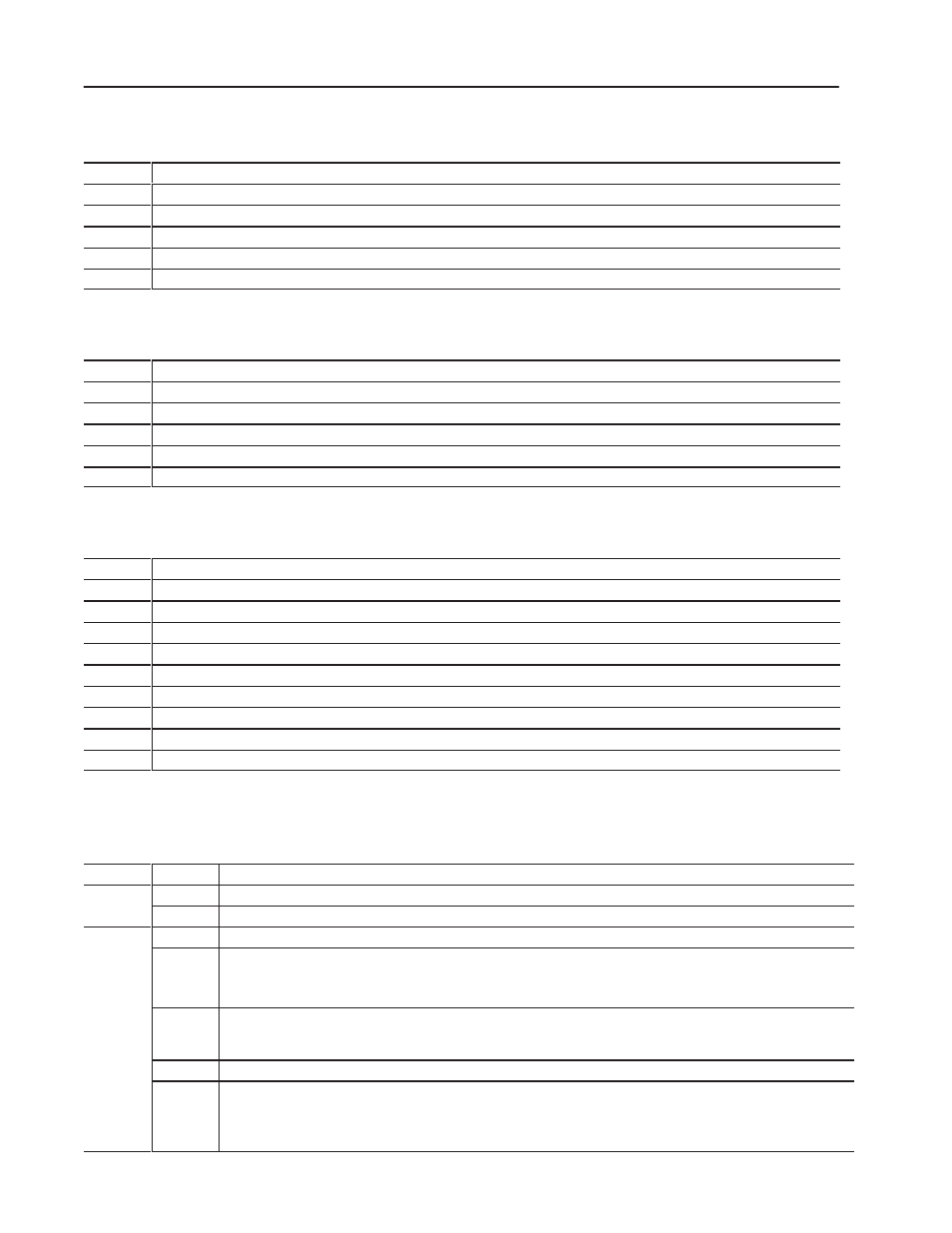
Screw Rotate Jog Set-output Values
The module sets its outputs to these values when DYC01-B09 = 1.
Word
Description
JGC09
Output #1 Set-output Value for Screw Rotate Jogs [19]
JGC10
Output #2 Set-output Value for Screw Rotate Jogs [19]
JGC11
Output #3 Set-output Value for Screw Rotate Jogs [19]
JGC12
Output #4 Set-output Value for Screw Rotate Jogs [19]
JGC13-16
RFU
Ram (Screw) Forward Jog Set-output Values
The module sets its outputs to these values when DYC01-B10 = 1.
Word
Description
JGC17
Output #1 Set-output Value for Ram (Screw) Forward Jogs [19]
JGC18
Output #2 Set-output Value for Ram (Screw) Forward Jogs [19]
JGC19
Output #3 Set-output Value for Ram (Screw) Forward Jogs [19]
JGC20
Output #4 Set-output Value for Ram (Screw) Forward Jogs [19]
JGC21-24
RFU
Ram (Screw) Reverse Jog Set-output Values
The module sets its outputs to these values when DYC01-B11 = 1.
Word
Description
JGC25
Output #1 Set-output Value for Ram (Screw) Reverse Jogs [19]
JGC26
Output #2 Set-output Value for Ram (Screw) Reverse Jogs [19]
JGC27
Output #3 Set-output Value for Ram (Screw) Reverse Jogs [19]
JGC28
Output #4 Set-output Value for Ram (Screw) Reverse Jogs [19]
JGC29
Output #5 Set-output Value for Ram (Screw) Reverse Jogs [19]
JGC30
Output #6 Set-output Value for Ram (Screw) Reverse Jogs [19]
JGC31
Output #7 Set-output Value for Ram (Screw) Reverse Jogs [19]
JGC32
Output #8 Set-output Value for Ram (Screw) Reverse Jogs [19]
JGC33-64
RFU
Bit-mapped Control Words
Word
Bit
Description
MCC01
B00 - B07
Block ID 00000001
M
1
B08-15
Reserved for the module. Do not use.
MCC02
MCC Configuration Selections
M
2
B00
Data Range Selection
= n li h nit ( nche and P )
0 = English Units (Inches and PSI)
1 = Metric Units (Millimeters and Bar)
B01
Module designation for co-injection
0 = QIA
1 = QIB
B02
RFU
B03
Module Inputs
= nvalid
0 = Invalid
1 = equired election The odule con i ure it el a a 1- lot odule containin our in ut and our out ut
1 = Required selection The module configures itself as a 1-slot module containing four inputs and four outputs,
and accesses bits MCC02-B04 and MCC02-B05 to determine layout of its inputs.
MCC – Module Configuration
Command Block