Flow chart for co- injection programming, Flow chart for co-injection programming – Rockwell Automation 1771-QI,D17716.5.126 PLASTIC MOLD.MODULE User Manual
Page 138
5–6
Sequencing Co-injection
Publication 1771-6.5.126 – March 1998
Your ladder logic must monitor conditions and set command bits for QI
modules to step through the various algorithms of co-injection. For the
example of ABA, we present a list of parameters, a diagram, and a flow
chart that indicates the logic that QI modules expect to see. (Remember
that screw position values decrease going toward the mold.)
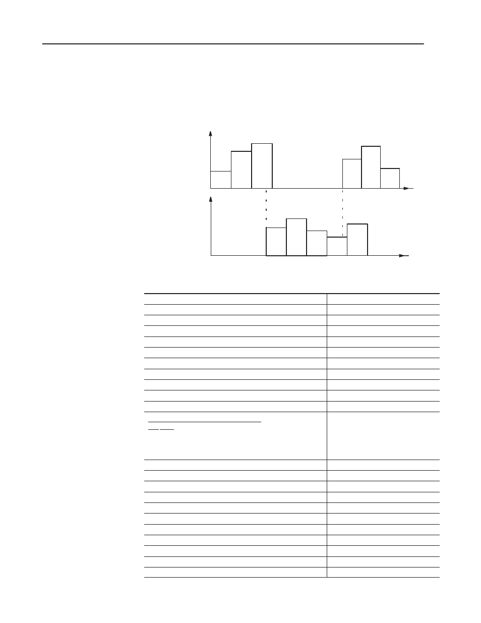
Co-injection Diagram for ABA
QI(A)’s Injection Profile
aaa
1
2
3
4
5
6
2
3
1
QI(B)’s Injection Profile
0
bbb
4
5
0
Pressure
Pressure
Time
Time
Suspended til other
reaches position aaa
stored in IPCB08
Suspended til other
reaches position bbb
stored in IPC08.
List of Co-injection Parameters for ABA
Description (for suspension of injection profile):
with Word/Bit:
start injection sequence
DYC02-BO4 = 1 or DYCB02-BO4 = 1
enable suspension at start (Start at opposite screw position IPC08.)
DYCB03-BO4 = 1
disable automatic sequence into pack/hold
IPCB02-B08 = 1
enable own suspension on own screw position IPC56
IPC02-B10 = 1
optional time delay after reaching opposite screw position
IPC07 and IPCB07
screw position of other to exit suspension
IPCB08 = aaa or IPC08 = bbb
set-outputs during injection
INC09-16 or INCB09-16
set outputs during pause before other goes automatically to P/H
INCB33-36
set-outputs during suspended injection
INC61-64
screw position of own to start suspension
IPC56 = aaa
set-output mode during suspended injection
B12 B11 (IPC54 or 55 overrides corresponding value in INC61-64)
0 0
=
apply
all four set-outputs stored in INC61-64
0
1
= control injection valve with pressure setpoint in IPC55
1
0
= control injection valve with velocity setpoint in IPC54
1
1
= error condition
IPC02-B12, B11
IPCB02-B12, B11
velocity setpoint for closed-loop control during suspended injection
IPC54
pressure setpoint for closed-loop control during suspended injection
IPC55
time limit for injection transition (indicated by IPS06.B00)
IPC60 & IPCB60
screw position limit for injection transition (indicated by IPS06.B01)
IPC61 & IPCB61
screw pressure limit for injection transition (indicated by IPS06.B02)
IPC62 & IPCB62
cavity pressure limit for injection transition (indicated by IPS06.B03)
IPC63 & IPCB63
status bit: injection profile complete
SYS02-B04
status bit: injection suspended
SYS03-B00
status bits: handshaking for change-over of input #3
SYS14-B14, -B15
status bit: injection profile in progress
SYS21-B04
status bit: end of injection profile, set-outputs in progress
SYS22-B04
Flow Chart for
Co-injection Programming