3 registers controlling clock generator – NEC PD78F9488 User Manual
Page 98
CHAPTER 5 CLOCK GENERATOR
98
User’s Manual U15331EJ4V1UD
5.3 Registers Controlling Clock Generator
The clock generator is controlled by the following four registers.
• Processor clock control register (PCC)
• Subclock oscillation mode register (SCKM)
• Subclock control register (CSS)
• Subclock selection register (SSCK) (
µPD78F9488, 78F9489 only)
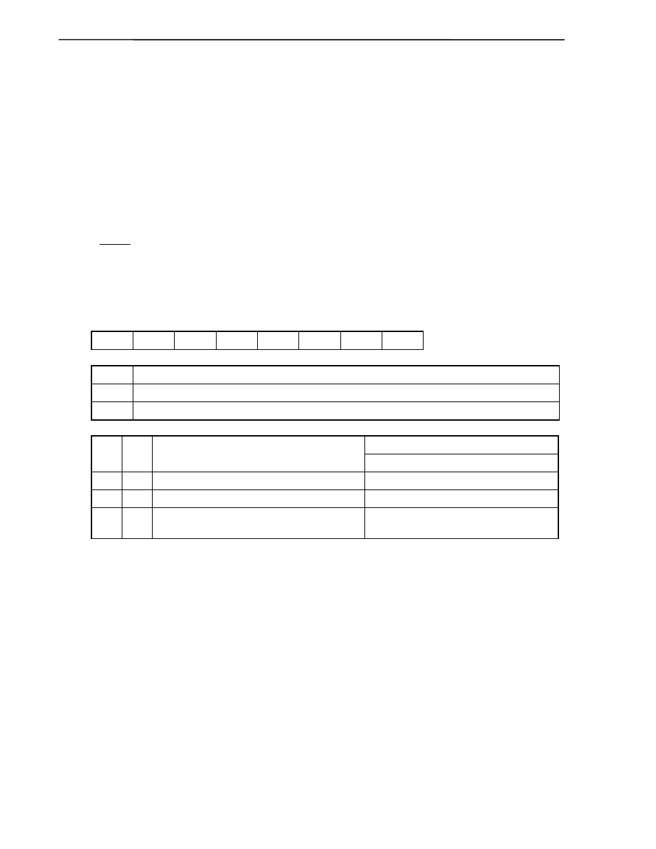
(1) Processor clock control register (PCC)
This register is used to select the CPU clock and set the frequency division ratio.
PCC is set with a 1-bit or 8-bit memory manipulation instruction.
RESET input sets this register to 02H.
Figure 5-3. Format of Processor Clock Control Register
Symbol
<7>
6 5 4 3 2
<1>
0
Address
After
reset
R/W
PCC
MCC
0 0 0 0 0
PCC1
0
FFFBH
02H
R/W
MCC
Main system clock oscillator operation control
0
Operation
enabled
1
Operation
stopped
Minimum instruction execution time: 2/f
CPU
CSS0 PCC1
CPU clock (f
CPU
) selection
Note
f
X
= 5.0 MHz or f
XT
= 32.768 kHz
0 0
f
X
0.4
µ
s
0 1
f
X
/2
2
1.6
µ
s
1
×
f
XT
/2
4f
XT
(when
×4 multiplication circuit is used)
122
µ
s
15.26
µ
s (when
×4 multiplication circuit is used)
Note The CPU clock is selected by a combination of flag settings in the PCC and CSS registers. (Refer to
5.3 (3) Subclock control register (CSS).)
Cautions 1. Always set bits 0 and 2 to 6 to 0.
2. MCC can be set only when the subsystem clock is selected as the CPU clock.
Setting MCC to 1 while the main system clock is operating is invalid.
Remarks 1. f
X
: Main system clock oscillation frequency
2. f
XT
: Subsystem clock oscillation frequency