NEC PD78F9488 User Manual
Page 297
CHAPTER 16 INTERRUPT FUNCTIONS
User’s Manual U15331EJ4V1UD
297
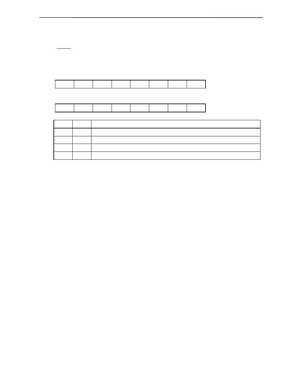
(3) External interrupt mode registers (INTM0, INTM1)
These registers are used to specify the valid edge for INTP0 to INTP3.
INTM0 and INTM1 are set with an 8-bit memory manipulation instruction.
RESET input sets these registers to 00H.
Figure 16-4. Format of External Interrupt Mode Registers
Symbol
7 6 5 4 3 2 1 0
Address
After
reset
R/W
INTM0 ES21 ES20 ES11 ES10 ES01 ES00 0
0 FFECH 00H R/W
Symbol
7 6 5 4 3 2 1 0
Address
After
reset
R/W
INTM1
0 0 0 0 0 0
ES31
ES30
FFEDH
00H
R/W
ESn1
ESn0
INTPn valid edge selection
0 0
Falling
edge
0 1
Rising
edge
1 0
Setting
prohibited
1
1
Both rising and falling edges
Remark n = 0, 1, 2, and 3
Cautions 1. Always set bits 0 and 1 of INTM0, and 2 to 7 of INTM1 to 0.
2. Before setting INTM0 and INTM1, set (1) the interrupt mask flags (PMK0 to PMK3) to
disable interrupts.
To enable interrupts, clear (0) the interrupt request flags (PIF0 to PIF3), then clear (0) the
interrupt mask flags (PMK0 to PMK3).