NEC PD78F9488 User Manual
Page 203
CHAPTER 11 SERIAL INTERFACE 20
User’s Manual U15331EJ4V1UD
203
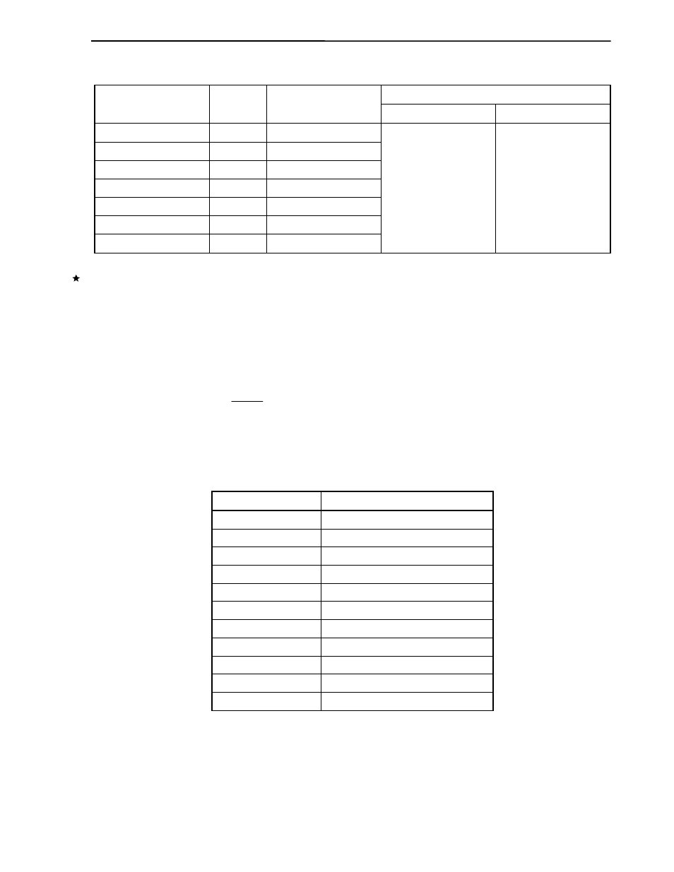
Table 11-5. Example of Relationship Between System Clock and Baud Rate
Error (%)
Baud Rate (bps)
n
BRGC20 Set Value
f
X
= 5.0 MHz
f
X
= 4.9152 MHz
1,200 8 70H
2,400 7 60H
4,800 6 50H
9,600 5 40H
19,200 4 30H
38,400 3 20H
76,800 2 10H
1.73 0
Caution Do not select n = 1 during operation at f
X
> 2.5 MHz because the resulting baud rate exceeds the
rated range.
(ii) Generation of baud rate transmit/receive clock from external clock input to ASCK20 pin
The transmit/receive clock is generated by dividing the clock input from the ASCK20 pin. The baud
rate of a clock generated from the clock input to the ASCK20 pin is estimated by using the following
expression.
[Baud rate] = [bps]
f
ASCK
: Frequency of clock input to ASCK20 pin
Table 11-6. Relationship Between ASCK20 Pin Input Frequency
and Baud Rate (When BRGC20 Is Set to 80H)
Baud Rate (bps)
ASCK20 Pin Input Frequency (kHz)
75 1.2
150 2.4
300 4.8
600 9.6
1,200 19.2
2,400 38.4
4,800 76.8
9,600 153.6
19,200 307.2
31,250 500.0
38,400 614.4
f
ASCK
16