NEC PD78F9488 User Manual
Page 295
CHAPTER 16 INTERRUPT FUNCTIONS
User’s Manual U15331EJ4V1UD
295
(1) Interrupt request flag registers (IF0 to IF2)
An interrupt request flag is set (1) when the corresponding interrupt request is generated, or when an
instruction is executed. It is cleared (0) when the interrupt request is acknowledged, when the RESET signal
is input, or when an instruction is executed.
IF0 to IF2 are set with a 1-bit or 8-bit memory manipulation instruction.
RESET input sets these registers to 00H.
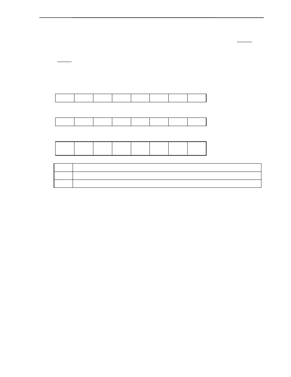
Figure 16-2. Format of Interrupt Request Flag Registers
Symbol
<7> <6> <5> <4> <3> <2> <1> <0>
Address
After
reset
R/W
IF0 CSIIF10
SRIF20
RINIF
Note
PIF3 PIF2 PIF1 PIF0 WDTIF
FFE0H 00H R/W
Symbol
<7> <6> <5> <4> <3> <2> <1> <0>
Address
After
reset
R/W
IF1
WTIF ADIF0 TMIF61 TMIF60 TMIF50 TMIF20 WTIIF STIF20 FFE1H 00H
R/W
Symbol 7
6 <5> <4> <3> <2> <1> <0>
Address
After
reset
R/W
IF2 0 0
KRIF01
Not
e
DFULLIF
Not
e
RENDIF
Note
GPIF
Note
RERRIF
Note
KRIF00 FFE2H
00H
R/W
×× IF×
Interrupt request flag
0
No interrupt request signal generated
1
An interrupt request signal is generated and an interrupt request made
Note
µPD789489 and 78F9489 only
Cautions 1. The WDTIF flag can be read/written only when the watchdog timer is being used as an
interval timer. It must be cleared to 0 if the watchdog timer is used in watchdog timer
mode 1 or 2.
2. Because P30 to P33 function alternately as external interrupts, when the output level
changes after the output mode of the port function is specified, the interrupt request
flag will be inadvertently set. Therefore, be sure to preset the interrupt mask flag (PMK0
to PMK3) before using the port in output mode.