Appendix d revision history – NEC PD78F9488 User Manual
Page 385
User’s Manual U15331EJ4V1UD
385
APPENDIX D REVISION HISTORY
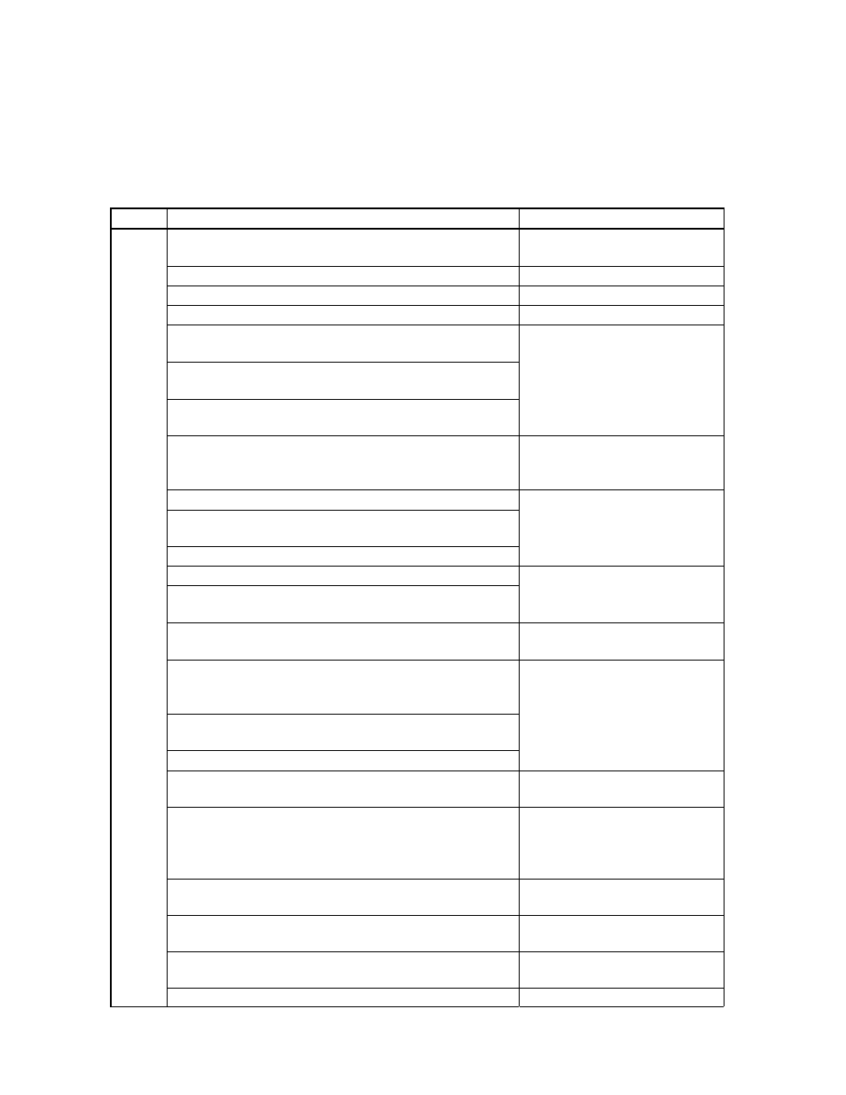
The following table shows the revision history up to this edition. The “Applied to:” column indicates the chapters of
each edition in which the revision was applied.
(1/4)
Edition
Major Revision from Previous Edition
Applied to:
Correction of number of vectored interrupt sources in 1.7
Overview of Functions
CHAPTER 1 GENERAL
Change of V
PP
pin handling
CHAPTER 2 PIN FUNCTIONS
Change of block diagrams of P23 and P24
CHAPTER 4 PORT FUNCTIONS
Addition of Note on feedback resistor
CHAPTER 5 CLOCK GENERATOR
Correction of bit name of bit 0 of timer mode control registers 60
and 61 (TMC60, TMC61)
Addition of Caution on carrier generator output control register 60
(TCA60)
Correction of values in Table 7-8 Square-Wave Output Range of
Timer 61
CHAPTER 7 8-BIT TIMERS 50, 60,
AND 61
Change of Figure 10-4 Basic Operation of 10-Bit A/D Converter
and Figure 10-5 Relationship Between Analog Input Voltage
and A/D Conversion Result
CHAPTER 10 10-BIT A/D
CONVERTER
Modification of Figure 11-1 Block Diagram of Serial Interface 20
Modification of description on PE20 flag in Figure 11-5 Format of
Asynchronous Serial Interface Status Register 20
Addition of description on UART receive data read
CHAPTER 11 SERIAL INTERFACE
20
Change of Figure 13-2 LCD Controller/Driver Block Diagram
Addition of 13.8 Supplying LCD Drive Voltages V
LC0
, V
LC1
, and
V
LC2
CHAPTER 13 LCD
CONTROLLER/DRIVER
Modification of description on serial interface 20 in Table 17-1
Status of Hardware After Reset
CHAPTER 17 RESET FUNCTION
Addition of description on subsystem clock
×4 multiplier and pull-up
resistor of port 5 in Table 18-1 Differences Between
µ
PD78F9488 and Mask ROM Version
Revision of contents about flash memory programming as 18.1
Flash Memory Characteristics
Addition of 18.2 Cautions on
µ
PD78F9488
CHAPTER 18
µ
PD78F9488
Addition of electrical specifications
CHAPTER 21 ELECTRICAL
SPECIFICATIONS
Addition of characteristics curves of LCD controller/driver
(reference values)
CHAPTER 22 CHARACTERISTICS
CURVES OF LCD
CONTROLLER/DRIVER
(REFERENCE VALUES)
Addition of package drawings
CHAPTER 23 PACKAGE
DRAWINGS
Addition of recommended soldering conditions
CHAPTER 24 RECOMMENDED
SOLDERING CONDITIONS
Revision of APPENDIX A DEVELOPMENT TOOLS
Deletion of description on embedded software
APPENDIX A DEVELOPMENT
TOOLS
2nd
Addition of revision history
APPENDIX C REVISION HISTORY