NEC PD78F9488 User Manual
Page 244
CHAPTER 12 SERIAL INTERFACE 1A0
244
User’s Manual U15331EJ4V1UD
(c) Repeat transmit mode
In this mode, data stored in the buffer RAM is transmitted repeatedly.
Serial transfer is started by writing any data to serial shift I/O register 1A0 (SIO1A0) when bit 7 (CSIE10)
of serial operation mode register 1A0 (CSIM1A0) is set to 1, and bit 7 (RE0) of automatic data
transmit/receive control register 0 (ADTC0) is set to 0.
Unlike the basic transmission mode, after the last byte (data in address FFA0H) has been transmitted,
the interrupt request flag (CSIIF10) is not set, the value at the time when the transmission was started is
set in automatic data transmit/receive address pointer 0 (ADTP0) again, and the buffer RAM contents
are transmitted again.
When a reception operation is not performed, the P25/SI10 pin can be used as a normal I/O port.
The repeat transmit mode operation timing is shown in Figure 12-13, and the operation flowchart in
Figure 12-14.
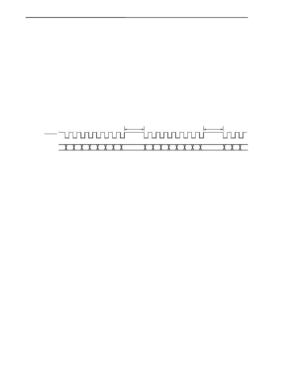
Figure 12-13. Repeat Transmit Mode Operation Timing
Caution Because, in the repeat transmit mode, a read is performed on the buffer RAM after the
transmission of one byte, the interval is included in the period up to the next
transmission. As the buffer RAM read is performed at the same time as CPU
processing, the maximum interval is dependent upon the CPU operation and the value
of automatic data transmit/receive interval specification register 0 (ADTI0) (refer to
12.4.3 (5) Interval time of automatic transmission/reception).
D7 D6 D5 D4 D3 D2 D1 D0
D7 D6 D5 D4 D3 D2 D1 D0
Interval
Interval
D7 D6 D5
SCK10
SO10