NEC PD78F9488 User Manual
Page 130
CHAPTER 7 8-BIT TIMERS 50, 60, AND 61
User’s Manual U15331EJ4V1UD
130
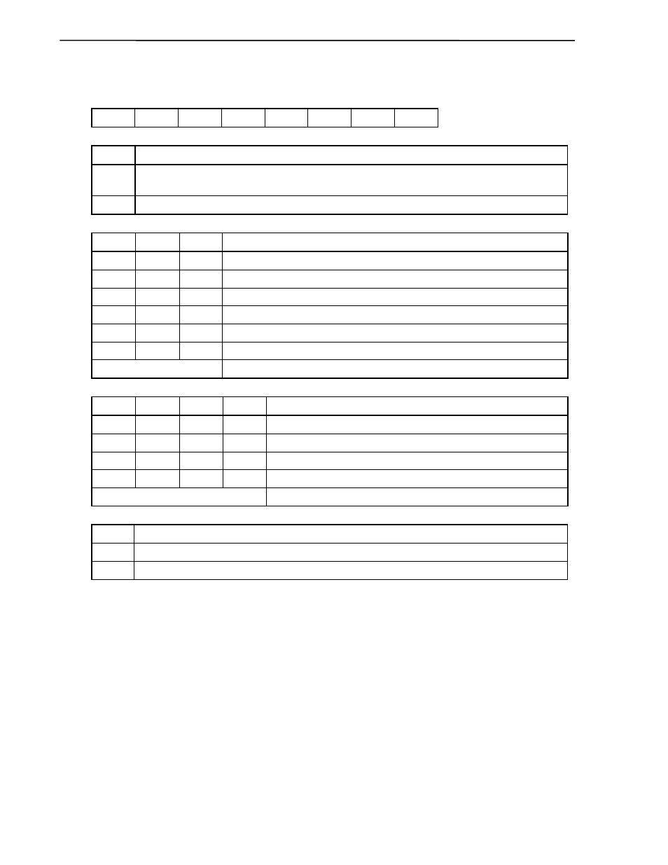
Figure 7-7. Format of 8-Bit Timer Mode Control Register 60
Symbol
<7>
6 5 4 3 2 1
<0>
Address
After
reset
R/W
TMC60 TCE60
0
TCL602 TCL601 TCL600 TMD601
TMD600
TOE600 FF4EH
00H
R/W
TCE60
Control of TM60 count operation
Note 1
0
Clear TM60 count value and stop operation (the count value is also cleared for TM50 in cascade connection
mode)
1
Start count operation (the count operation is also started for TM50 in cascade connection mode)
TCL602
TCL601
TCL600
Selection of timer 60 count clock
0 0 0
f
X
(5.0 MHz)
0 0 1
f
X
/2
2
(1.25 MHz)
0 1 0
f
TMI
0 1 1
f
TMI
/2
1 0 0
f
TMI
/2
2
1 0 1
f
TMI
/2
3
Other than above
Setting prohibited
TMD501 TMD500 TMD601 TMD600
Selection of operation mode for timer 60
Note 2
×
0
0
0
Stand-alone mode (8-bit counter mode)
0 1 0 1
16-bit
counter
mode (cascade connection mode)
0 0 1 1
Carrier
generator
mode
×
0
1
0
PPG output mode
Other than above
Setting prohibited
TOE600
Control of timer output
0
Output
disabled
1
Output
enabled
Notes 1. Since the count operation is controlled by TCE60 (bit 7 of TMC60) in cascade connection mode,
any setting for TCE50 is ignored.
2. The operation mode selection is set by a combination of the TMC50 and TMC60 registers.
Caution To manipulate TMC60, follow the setting procedure below.
<1> Set the TM60 count operation to stop.
<2> Set the operation mode and count clock.
<3> The count operation starts.
Remarks 1. f
X
:
Main system clock oscillation frequency
2. f
TMI
: External input clock frequency
3. The parenthesized values apply to operation at f
X
= 5.0 MHz.
4.
×: don’t
care