NEC PD78F9488 User Manual
Page 284
CHAPTER 15 REMOTE CONTROLLER RECEIVER (
µ
PD789489, 78F9489 ONLY)
User’s Manual U15331EJ4V1UD
284
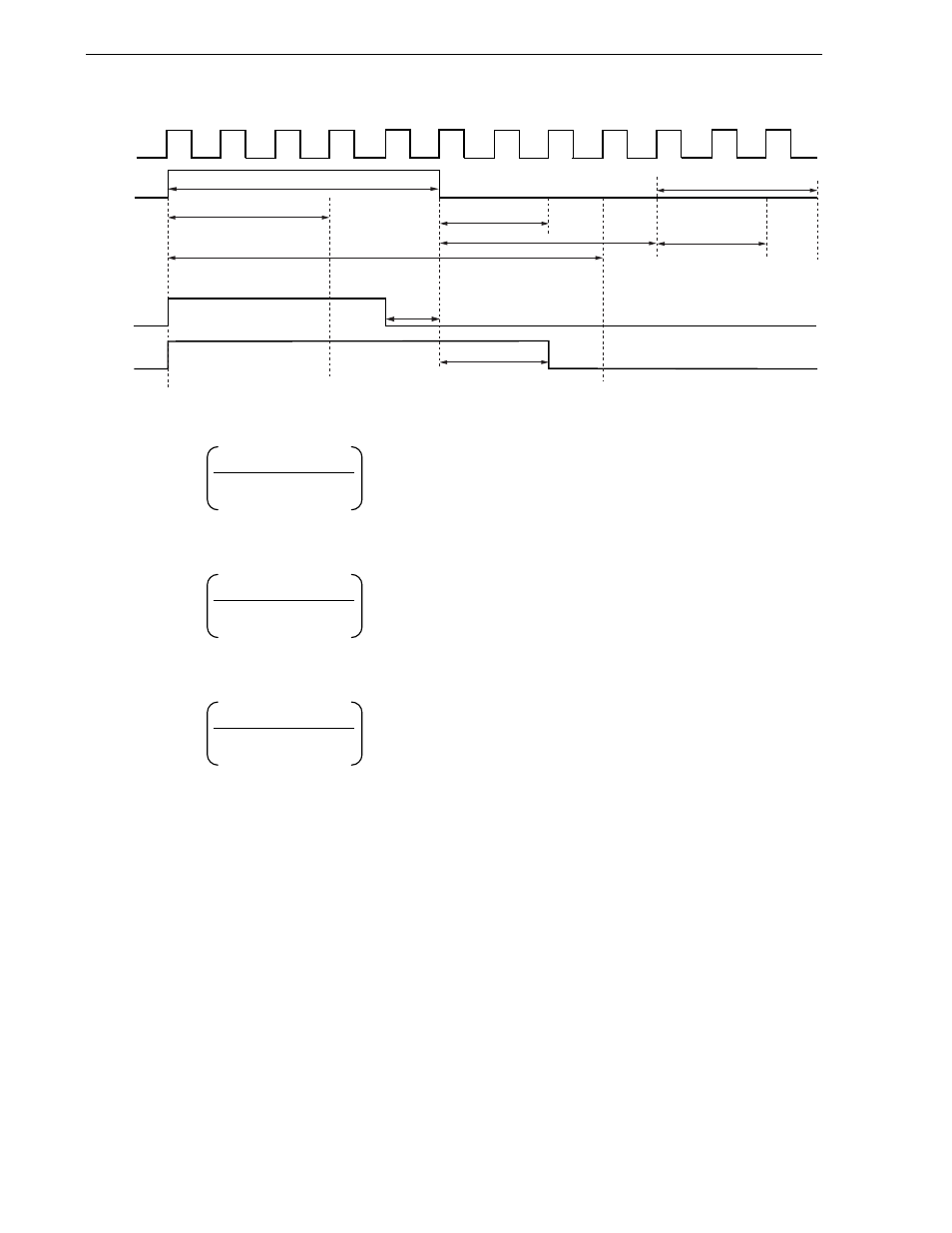
Figure 15-6. Setting Example (Where n1
= 1, n2 = 2)
RIN
RIN_2
T
W
RIN_1
Clock
RMGPHS/RMDH0S/RMDH1S
n1
n2
RMGPHL/RMDH0L/RMDH1L
RMDLS
RMDLL
T
WE
RMER
(1) Formula for RMGPHS, RMDLS, RMDH0S, and RMDH1S
− 2 − n1
(2) Formula for RMGPHL, RMDLL, RMDH0L, and RMDH1L
+ 1 + n2
(3) Formula for RMER
− 1
T
W
:
Width of RIN input waveform
1/f
PRS
: Width of internal operation clock cycle after division control by PRSEN
a: Tolerance
(%)
[ ]
INT
:
Round down the fractional portion of the value produced by the formula in the brackets.
n1, n2: Variables of waveform change caused by noise
Note1
T
WE
:
End width of RIN input
Note2
Notes 1. Set the values of n1 and n2 as required to meet the user
′s system specification.
2. This end width is counted after RMDLL.
The low-level width actually required after the last data has been received is as follows:
(RMDLL + 1 + RMER + 1)
× (width of internal operation clock cycle after division control by PRSEN)
T
W
× (1 − a/100)
1/f
PRS
INT
T
W
× (1 + a/100)
1/f
PRS
INT
T
WE
× (1 − a/100)
1/f
PRS
INT