NEC PD78F9488 User Manual
Page 111
CHAPTER 6 16-BIT TIMER 20
User’s Manual U15331EJ4V1UD
111
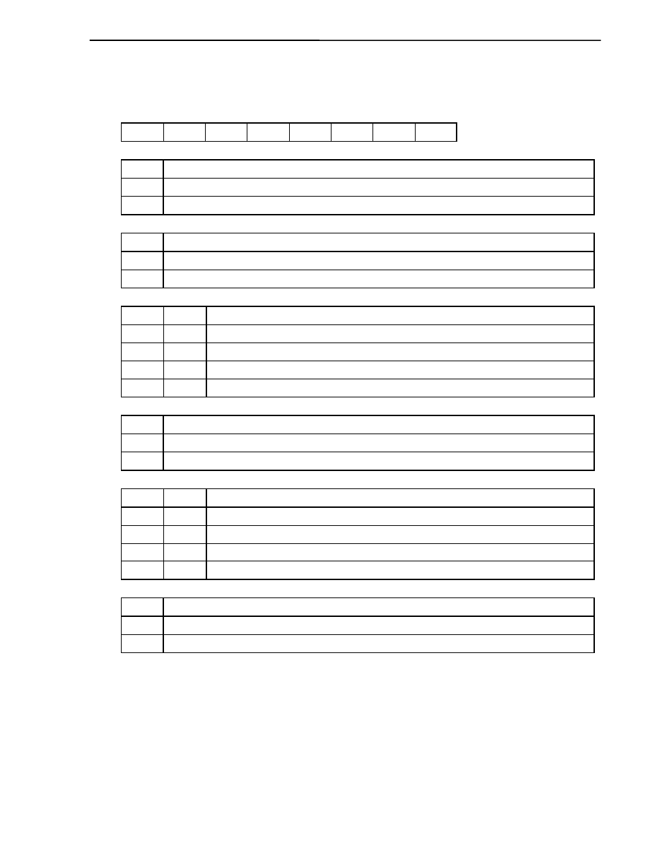
Figure 6-2. Format of 16-Bit Timer Mode Control Register 20
Symbol
<7>
<6>
5 4 3 2 1
<0>
Address
After
reset
R/W
TMC20 TOD20 TOF20 CPT201 CPT200 TOC20 TCL201 TCL200 TOE20 FF48H
00H
R/W
Note 1
TOD20
Timer output data
0
Timer output is “0”
1
Timer output is “1”
TOF20
Set overflow flag
0
Reset and clear by software
1
Set by overflow of 16-bit timer
CPT201 CPT200
Selection of capture edge
0
0
Capture operation disabled
0
1
Rising edge of CPT20 pin
1
0
Falling edge of CPT20 pin
1
1
Both edges of CPT20 pin
TOC20
Timer output data inversion control
0
Inversion
disabled
1
Inversion
enabled
TCL201 TCL200
Selection of count clock for 16-bit timer counter 20
0
0
Timer 61 interrupt signal
0 1
f
X
(5.0 MHz)
Notes 2, 3
1 0
f
X
/2
2
(1.25 MHz)
Note 4
1 1
f
X
/2
5
(156.25 kHz)
Note 4
TOE20
Output control for 16-bit timer counter 20
0
Output disabled (port mode)
1
Output
enabled
Notes 1. Bit 7 is read-only.
2.
If f
X
is selected for the count clock, the signal cannot be used as a capture signal.
3.
In a read operation, set the CPU clock as the high-speed main clock (PCC1 = 0, CSS = 0).
4.
In a read operation, set the CPU clock as the main clock (CSS = 0).
Remarks 1. f
X
: Main system clock oscillation frequency
2.
The parenthesized values apply to operational f
X
= 5.0 MHz.