NEC PD78F9488 User Manual
Page 194
CHAPTER 11 SERIAL INTERFACE 20
194
User’s Manual U15331EJ4V1UD
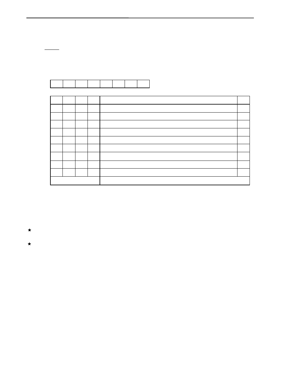
(4) Baud rate generator control register 20 (BRGC20)
BRGC20 is used to specify the serial clock for serial interface 20.
BRGC20 is set with an 8-bit memory manipulation instruction.
RESET input sets BRGC20 to 00H.
Figure 11-6. Format of Baud Rate Generator Control Register 20
TPS203
0
0
0
0
0
0
0
0
1
Selection of baud rate generator source clock
TPS203 TPS202 TPS201 TPS200
0
0
0
0
BRGC20
Symbol
Address
After reset
R/W
FF73H
00H
R/W
7
6
5
4
3
2
1
0
TPS202
0
0
0
0
1
1
1
1
0
f
X
/2
f
X
/2
2
f
X
/2
3
f
X
/2
4
f
X
/2
5
f
X
/2
6
f
X
/2
7
f
X
/2
8
External clock input to the ASCK20 pin
Note
Setting prohibited
(2.5 MHz)
(1.25 MHz)
(625 kHz)
(313 kHz)
(156 kHz)
(78.1 kHz)
(39.1 kHz)
(19.5 kHz)
Other than above
TPS201
0
0
1
1
0
0
1
1
0
TPS200
0
1
0
1
0
1
0
1
0
n
1
2
3
4
5
6
7
8
−
Note An external clock can be used only in UART mode.
Cautions 1. When writing to BRGC20 during a communication operation, the output of the baud
rate generator is disrupted and communications cannot be performed normally. Be
sure not to write to BRGC20 during a communication operation.
2. Be sure not to select n = 1 in UART mode when f
X
> 2.5 MHz because the baud rate will
exceed the rated range.
3. When the external input clock is selected, set input mode by setting bit 0 of port mode
register 2 (PM2) to 1.
Remarks 1. f
X
: Main system clock oscillation frequency
2. n: Values determined by the settings of TPS200 to TPS203 (1
≤ n ≤ 8)
3. The parenthesized values apply to operation at f
X
= 5.0 MHz.