7 overview of functions – NEC PD78F9488 User Manual
Page 35
CHAPTER 1 GENERAL
User’s Manual U15331EJ4V1UD
35
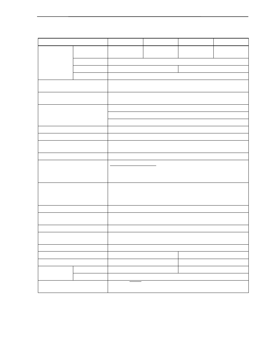
1.7 Overview of Functions
(1/2)
Item
µ
PD789488
µ
PD78F9488
µ
PD789489
µ
PD78F9489
ROM
32 KB
32 KB (flash
memory)
48 KB
48 KB (flash
memory)
High-speed RAM
1024 bytes
Low-speed RAM
−
512 bytes
Internal memory
LCD display RAM
28 bytes
Main system clock
(oscillation frequency)
Ceramic/crystal oscillation (1.0 to 5.0 MHz)
Subsystem clock
(oscillation frequency)
Crystal oscillation (32.768 kHz)
0.4
µ
s/1.6
µ
s (@5.0 MHz operation with main system clock)
122
µ
s (@32.768 kHz operation with subsystem clock)
Minimum instruction execution time
15.26
µ
s (@131 kHz operation with
×4 subsystem clock)
Subsystem clock multiplication function
×4 multiplication circuit (operating supply voltage: V
DD
= 2.7 to 5.5 V)
Note 1
General-purpose registers
8 bits
× 8 registers
Instruction set
• 16-bit operations
• Bit manipulation (set, reset, test) etc.
Multiplier 8
bits
× 8 bits = 16 bits
I/O ports
Total:
45
Note 2
CMOS I/O:
29
CMOS input:
12
N-ch open-drain I/O:
4
Timers
• 16-bit timer:
1 channel
• 8-bit timer:
3 channels
• Watch timer:
1 channel
• Watchdog timer: 1 channel
Timer outputs
4
Serial interface
UART/3-wire serial I/O mode: 1 channel
3-wire serial I/O mode (with automatic transfer function): 1 channel
A/D converter
10-bit resolution
× 8 channels
LCD controller/driver
• Segment signal outputs: 28
Note 3
• Common signal outputs: 4
Power supply method for LCD drive
Internal voltage amplification method
Infrared remote control reception function Not provided
Provided
Key return detection function
8 pins
16 pins
Maskable
Internal: 11, External: 5
Internal: 16, External: 6
Vectored interrupt
sources
Non-maskable Internal:
1
Reset
• Reset by RESET signal input
• Internal reset by watchdog timer
Notes 1. Whether a circuit to multiply the clock by 4 is used or not is selected by a mask option or the subclock
selection register.
2. 12 pins are used either as a port function or LCD segment output selected by a mask option or port
function register.