2 communication mode – NEC PD78F9488 User Manual
Page 321
CHAPTER 19 FLASH MEMORY VERSION
User’s Manual U15331EJ4V1UD
321
19.1.2 Communication mode
Use the communication mode shown in Table 19-2 to perform communication between the dedicated flash
programmer and
µPD78F9488 or 78F9489.
Table 19-2. Communication Mode List
TYPE Setting
Note 1
CPU Clock
Communication
Mode
COMM
PORT
SIO Clock
In Flashpro
On Target Board
Multiple
Rate
Pins Used
Number of V
PP
Pulses
3-wire serial I/O
SIO ch-0
(3-wired,
sync.)
SI20/RxD20/P22
SO20/TxD20/P21
SCK20/ASCK20/
P20
0
3-wire serial I/O
with handshake
SIO ch-3
+ handshake
100 Hz to
1.25
MHz
Note 2
1, 2, 4, 5
MHz
Note 3
1 to 5 MHz
Note
2
1.0
SI20/RxD20/P22
SO20/TxD20/P21
SCK20/ASCK20/
P20
P11 (HS)
3
UART
UART ch-0
(Async.)
4,800 to
76,800 bps
Notes 2, 4
5 MHz
Note 5
4.91 or
5 MHz
Note 2
1.0
RxD20/SI20/P22
TxD20/SO20/P21
8
Notes 1. Selection items for TYPE settings on the dedicated flash programmer (Flashpro III (part no. FL-PR3,
PG-FP3)/Flashpro IV (part no. FL-PR4, PG-FP4)).
2. The possible setting range differs depending on the voltage. For details, refer to CHAPTER 22
ELECTRICAL SPECIFICATIONS (
µPD789488, 78F9488, 789489, 78F9489).
3. Only 2 MHz or 4 MHz can be selected for Flashpro III.
4. Because signal wave slew also affects UART communication, in addition to the baud rate error,
thoroughly evaluate the slew.
5. Flashpro IV only. However, when using Flashpro III, be sure to select the clock of the resonator on the
board. UART cannot be used with the clock supplied by Flashpro III.
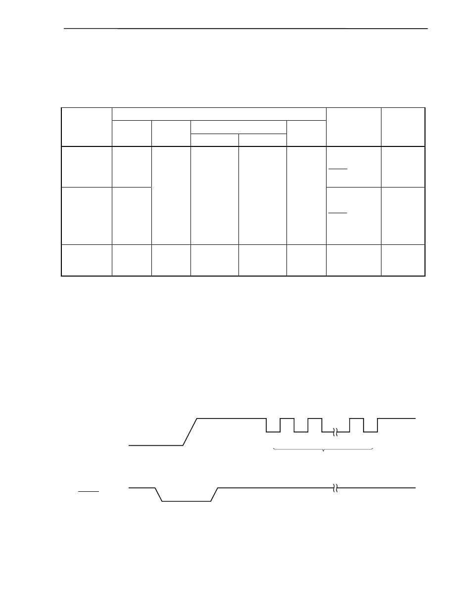
Figure 19-2. Communication Mode Selection Format
10 V
V
SS
V
DD
V
PP
V
DD
V
SS
RESET
1
2
n
V
PP
pulses