Related information, Rear panel diagram – FUJITSU SPARC T5440 User Manual
Page 31
Identifying Server Components
5
Related Information
■
“Front Panel Diagram” on page 3
■
■
“Detecting Faults Using LEDs” on page 30
Rear Panel Diagram
The rear panel provides access to system I/O ports, PCIe ports, Gigabit Ethernet
ports, power supplies, Locator button and LED, and system status LEDs.
FIGURE: Rear Panel Features on page 6
shows rear panel features on the SPARC
Enterprise T5440 server. For more detailed information about ports and their uses,
see the SPARC Enterprise T5440 Server Installation and Setup Guide. For a detailed
description of PCIe slots, see
“PCIe Device Identifiers” on page 96
.
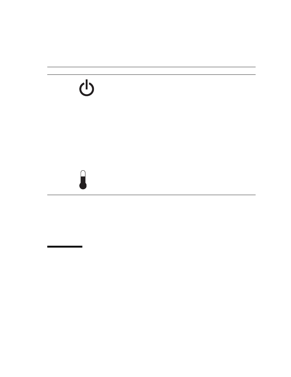
Power button
The recessed Power button toggles the system on or off.
• If the system is powered off, press once to power on.
• If the system is powered on, press once to initiate a graceful system shutdown.
• If the system is powered on, press and hold for 4 seconds to initiate an
emergency shutdown.
For more information about powering on and powering off the system, see the
SPARC Enterprise T5440 Server Administration Guide.
Fan Fault LED
(amber)
TOP
FAN
Provides the following operational fan indications:
• Off – Indicates a steady state, no service action is required.
• Steady on – Indicates that a fan failure event has been acknowledged and a
service action is required on at least one of the fan modules.
Power Supply
Fault LED
(amber)
REAR
PS
Provides the following operational PSU indications:
• Off – Indicates a steady state, no service action is required.
• Steady on – Indicates that a power supply failure event has been
acknowledged and a service action is required on at least one PSU.
Overtemp LED
(amber)
Provides the following operational temperature indications:
• Off – Indicates a steady state, no service action is required.
• Steady on – Indicates that a temperature failure event has been acknowledged
and a service action is required.
TABLE:
Front Panel LEDs and Controls (Continued)
LED or Button
Icon
Description