5 brake power supply unit, 1) model, 2) specifications – Yaskawa Sigma II Series SGMVH User Manual
Page 98: 3) dimensional drawing (4) internal circuits
5.5 Peripheral Devices
5
Specifications and Dimensional Drawings of Cables and Peripheral Devices
5-17
5.5.5 Brake Power Supply Unit
(1) Model:
LPSE-2H01, LPDE-1H01
Contact Yaskawa Controls Co., Ltd.
• 200 V input: LPSE-2H01
• 100 V input: LPDE-1H01
(2) Specifications
• Rated output voltage: 90 VDC
• Maximum output current: 1.0 ADC
• Lead wire length: 500 mm each
• Maximum surrounding air temperature: 60
°C
• Lead wires: Color coded. Refer to the table below.
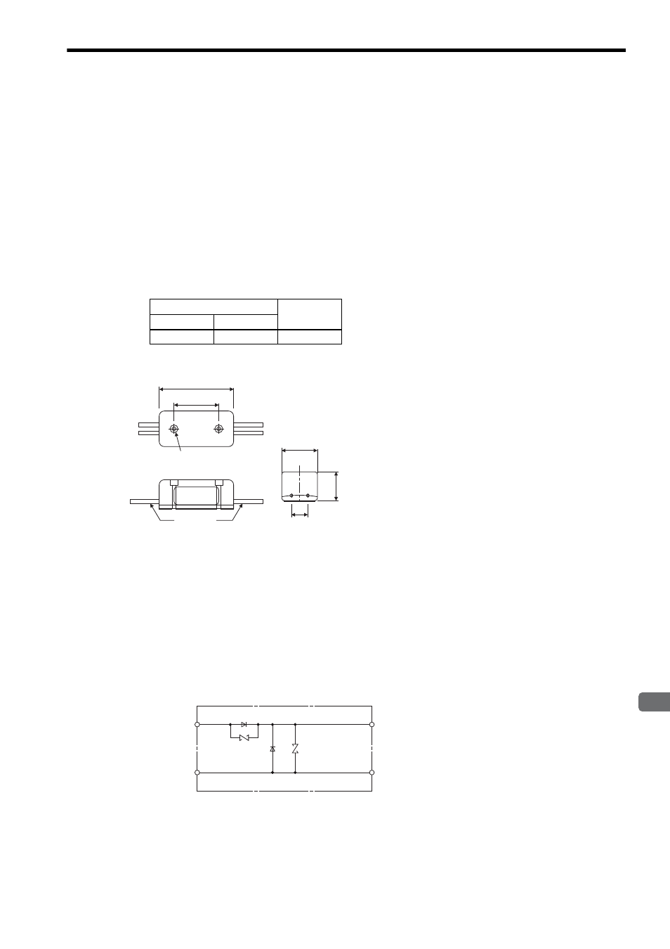
(3) Dimensional Drawing
(4) Internal Circuits
The brake power supply circuit can be opened and closed either on AC or DC side. However, if the wiring dis-
tance on DC side is too long, the brake circuit may not operate normally due to the influence of switching noises.
When switching the circuit on AC side, install a surge absorber model CR50500BL (sold as spark quencher) for
the brake power supply near the brake coil to reduce the influence of switching noises.
When switching the circuit on DC side, the influence of the switching noise is minimal, even without installing a
surge absorber. However, the surge voltage at switching may damage the brake coil. Install a surge absorber
near the brake coil to prevent the damage to the brake coil in addition to the built-in surge absorber.
(a) Internal Circuit for 200 VAC
Brake Power Supply Model: LPSE-2H01
AC Input End
Brake End
100 V
200 V
Blue/White
Yellow/White
Red/Blue
2 Mounting holes
φ3
(Spot facing
φ5.5
and 4 long
㧕
30
25
Units: mm
Nameplate
50
11
20
Lead wire
Yellow
White
Red
Black
AC side
180 to 230 V
Diode
Surge absorber
DC (Brake) side
No polarity
Surge absorber