Yaskawa Sigma II Series SGMVH User Manual
Page 311
11.2 Connection to Host Controller
11-9
11
Appendix
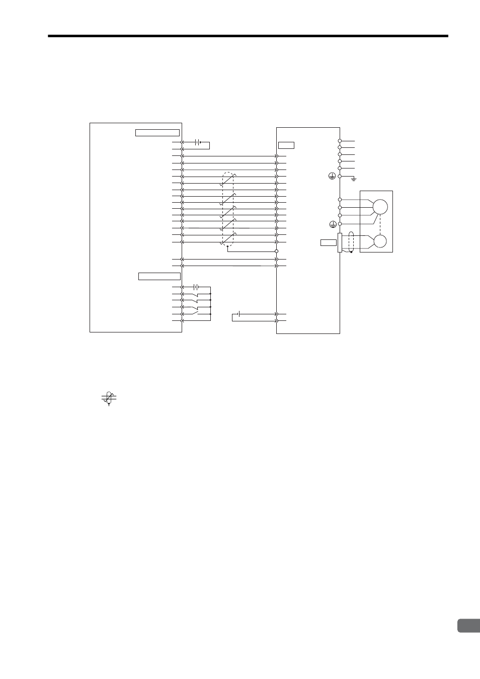
11.2.3 Example of Connection to OMRON’s Motion Control Unit
* 1. Connect when an absolute encoder is used.
When a battery is installed in the SERVOPACK, no battery is required for CN1 (between 21 and 22).
x
Battery for CN1: ER6VC3 (3.6 V, 2000 mAh)
x
Battery installed in the SERVOPACK: JZSP-BA01-1 (3.6 V, 1000 mAh)
* 2.
represents twisted-pair wires.
Note: 1. Only signals applicable to OMRON’s MC unit and Yaskawa’s SGDM/SGDH SERVOPACK are
shown in the diagram.
2. The main circuit power supply is a three-phase 200 VAC SERVOPACK input in the example.
The power supply and wiring must be in accordance with the power supply specifications of the
SERVOPACK to be used.
3. Note that incorrect signal connection will cause damage to the MC unit and SERVOPACK.
4. Open the signal lines not to be used.
5. The above connection diagram shows only X-axis connection. When using another axes, make
connection to the SERVOPACK in the same way.
6. The normally closed (N.C.) input terminals not to be used at the motion control unit I/O connec-
tor section must be short-circuited at the connector.
7. Make the setting so that the servo can be turned ON/OFF by the /S-ON signal.
CN2
CN1
3
4
5
16
8
9
13
12
11
19
15
14
18
1
5
6
1
19
20
35
34
20
4
BAT(-)
36
47
32
W
V
A(1)
B(2)
C(3)
D(4)
U
MC unit manufactured
by OMRON
DRV connector
Servomotor
SGDM/SGDH
SERVOPACK
Battery
(CV500-MC221/MC421)
(CS1W-MC221/MC421)
C200H-MC221
10
10
17
2
4
6
14
1
2
2
31
33
44
21
22
40
ALM+
/S-ON
/ALM-RST
SG
SEN
SG
SG
ALM-
FG
PAO
/PAO
/PBO
PBO
PCO
/PCO
V-REF
+24-IN
24V
24 VDC
24 VDC
input
24V input ground
X -axis alarm input
X-axis run reference output
X-axis alarm reset output
X-axis SEN signal ground
X-axis SEN signal output
X-axis feedback ground
X-axis phase-A input
X-axis phase-/A input
X-axis phase-B input
X-axis phase-/B input
X-axis phase-Z input
X-axis phase-/Z input
X-axis speed reference
Axis speed reference ground
24 V output
24 V output ground
I/O connector
24 V input
X-axis CW limit input
X-axis CCW limit input
X-axis immediate stop input
X-axis origin proximity input
24 V input ground
Shell
㧖2
㧖1
㧖1
㧖1
㧖1
㧖1
BAT(+)
M
Control
power supply
Main circuit
power supply
2.8 to 4.5 VDC
PG
L1C/r
L3/T
L2/S
L1/R
L2C/t