1 wiring main circuit, 1 names and functions of main circuit terminals, Caution – Yaskawa Sigma II Series SGMVH User Manual
Page 127
6 Wiring
6.1.1 Names and Functions of Main Circuit Terminals
6-2
6.1 Wiring Main Circuit
This section describes typical examples of main circuit wiring, functions of main circuit terminals, and the power
ON sequence.
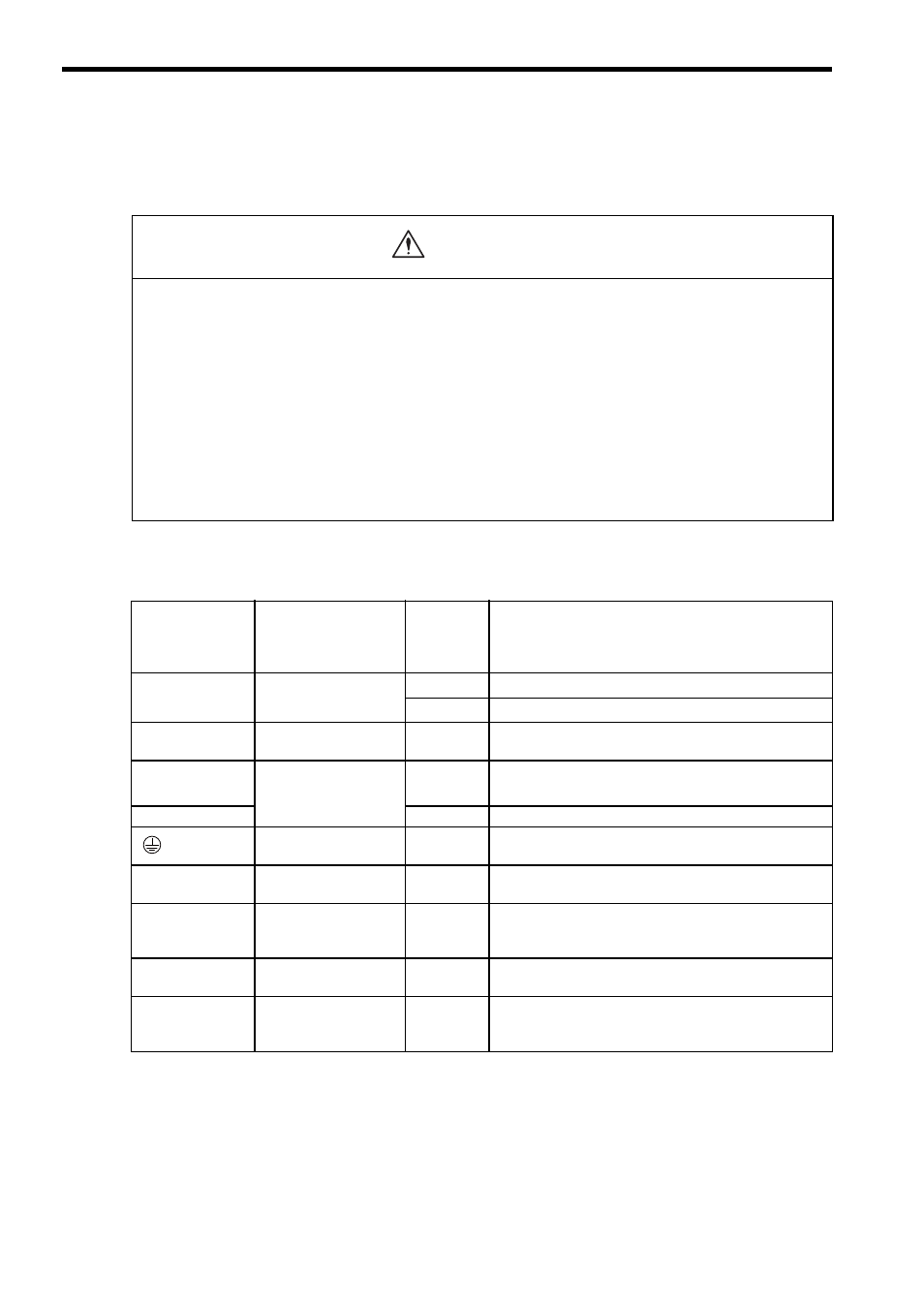
6.1.1 Names and Functions of Main Circuit Terminals
(1) SERVOPACK main circuit terminal functions and descriptions
• Do not bundle or run power and signal lines together in the same duct. Keep power and signal lines sepa-
rated by at least 300 mm.
Failure to observe this caution may result in malfunction.
• Use twisted-pair shielded wires or multi-core twisted pair shielded wires for signal and encoder (PG) feed-
back lines.
The maximum length is 3 m for reference input lines.
• Do not touch the power terminals for five minutes after turning power OFF because high voltage may still
remain in the SERVOPACK.
Make sure the charge indicator is turned OFF first before starting an inspection.
• Avoid frequently turning power ON and OFF.
Since the SERVOPACK has a capacitor in the power supply, a high charging current flows for 0.2 seconds when the
power is turned ON. Frequently turning the power ON and OFF causes main power devices such as capacitors and
fuses to deteriorate, resulting in unexpected problems.
Terminal Symbol
External Terminal
Name
Main
Circuit
Voltage
(V)
Functions
L1/R, L2/S,
L3/T
Main circuit power
supply input terminal
200
Three-phase 200 to 230 VAC
+10%, -15%
(50/60 Hz)
400
Three-phase 380 to 480 VAC
+10%,-15%
(50/60 Hz)
U, V, W
Servomotor
connection terminals
−
Connects to the servomotor.
L1C/r, L3C/t
Control circuit power
supply input terminal
200
Single-phase 200 to 220 VAC
+10%, -15%
(50 Hz)
Single-phase 200 to 230 VAC
+10%, -15%
(60 Hz)
DC24P, DC24N
400
24 VDC (
±15%)
Ground terminals
−
Connects to the power supply ground terminals and servo-
motor ground terminal.
B1, B2
Regenerative resistor
connection terminal
−
Connects to the regenerative resistor.
0 V, 380 V,
400 V, 440 V,
460 V, 480 V
Input terminal for
actuator control
400
Single-phase 380 to 480 VAC (50/60 Hz)
Power input terminals for the fan or contactor.
DU, DV, DW
Dynamic brake unit
connection terminal
−
Connects the dynamic brake unit.
DBON, DB24
Dynamic brake unit
connection terminal
−
Connects to the DBON and DB24 terminals of the dynamic
brake unit (only when using 37 kW or more SERVO-
PACK).
CAUTION