3 servopack internal block diagrams, 1 three-phase 200 v, 22 kw, 30 kw models – Yaskawa Sigma II Series SGMVH User Manual
Page 67
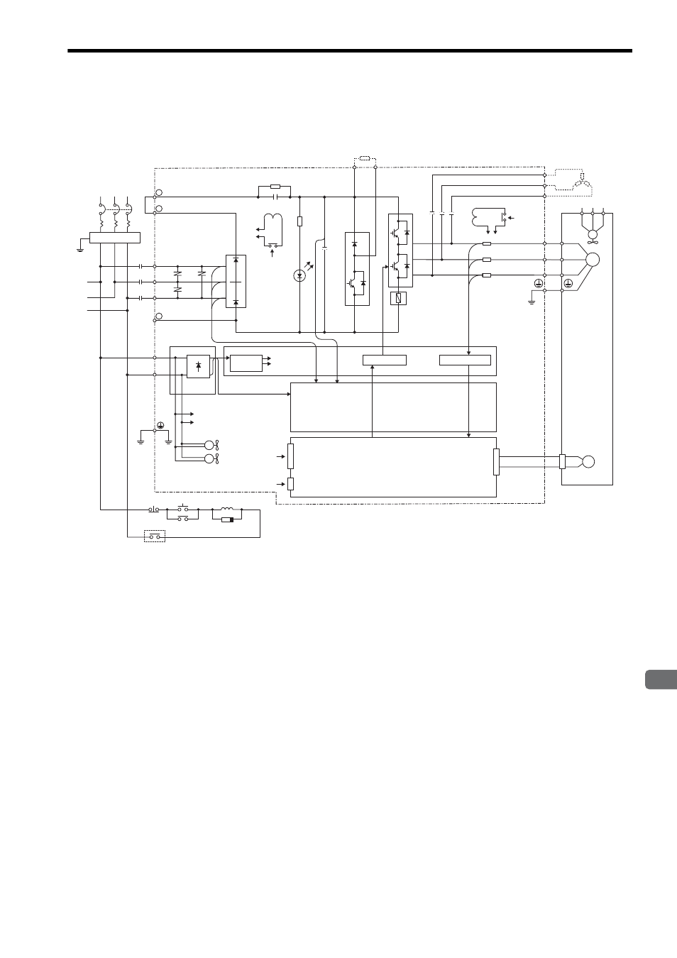
4.3 SERVOPACK Internal Block Diagrams
4
SER
VOP
ACK Specifications and Dimensional Drawings
4-7
4.3 SERVOPACK Internal Block Diagrams
4.3.1 Three-phase 200 V, 22 kW, 30 kW Models
FIL
R
S
T
1KM
L1/R
+ 1
+ 2
R1
B1
TRM7
TRM1
to
TRM6
FU1
to
3
C1 to
C4
B2
+
-
CHARGE
SA1 to SA3
3PWB
200 VAC
1KM
1KM
(5Ry)
Open during servo alarm
1CN
3CN
L1C/r
L3C/t
+5V
2PWB
2CN
PG
L2/S
L3/T
-
200 VAC
DCCT1
DCCT2
DCCT3
MC2
DU
DV
DW
U
V
W
U
R S
T
U V W
V
W
M
200
VAC
MC1
MC1
FAN
㨪ޓ
㨪ޓ
FAN1 to FAN2
1QF
Servomotor
Three-phase
200 to 230 VAC
(50/60 Hz)
Regenerative resistor (option)
DB resistor (option)
From
detection
circuit
From detection
circuit
DC/DC
converter
Power for
drive
Drive circuit
Current sensor
Sensor circuit
Position/speed calculation circuit
Control input
Digital operator
(personal computer)
Power OFF Power ON
Surge absorber
See also other documents in the category Yaskawa Equipment:
- Tag Generator (30 pages)
- MP3300iec (82 pages)
- 1000 Hz High Frequency (18 pages)
- 1000 Series (7 pages)
- PS-A10LB (39 pages)
- iQpump Micro User Manual (300 pages)
- 1000 Series Drive Option - Digital Input (30 pages)
- 1000 Series Drive Option - CANopen (39 pages)
- 1000 Series Drive Option - Analog Monitor (27 pages)
- 1000 Series Drive Option - CANopen Technical Manual (37 pages)
- 1000 Series Drive Option - CC-Link (38 pages)
- 1000 Series Drive Option - CC-Link Technical Manual (36 pages)
- 1000 Series Drive Option - DeviceNet (37 pages)
- 1000 Series Drive Option - DeviceNet Technical Manual (81 pages)
- 1000 Series Drive Option - MECHATROLINK-II (32 pages)
- 1000 Series Drive Option - Digital Output (31 pages)
- 1000 Series Drive Option - MECHATROLINK-II Technical Manual (41 pages)
- 1000 Series Drive Option - Profibus-DP (35 pages)
- AC Drive 1000-Series Option PG-RT3 Motor (36 pages)
- Z1000U HVAC MATRIX Drive Quick Start (378 pages)
- 1000 Series Operator Mounting Kit NEMA Type 4X (20 pages)
- 1000 Series Drive Option - Profibus-DP Technical Manual (44 pages)
- CopyUnitManager (38 pages)
- 1000 Series Option - JVOP-182 Remote LED (58 pages)
- 1000 Series Option - PG-X3 Line Driver (31 pages)
- SI-EN3 Technical Manual (68 pages)
- JVOP-181 (22 pages)
- JVOP-181 USB Copy Unit (2 pages)
- SI-EN3 (54 pages)
- SI-ET3 (49 pages)
- MECHATROLINK-III (35 pages)
- EtherNet/IP (50 pages)
- SI-EM3 (51 pages)
- 1000-Series Option PG-E3 Motor Encoder Feedback (33 pages)
- 1000-Series Option SI-EP3 PROFINET (56 pages)
- PROFINET (62 pages)
- AC Drive 1000-Series Option PG-RT3 Motor (45 pages)
- SI-EP3 PROFINET Technical Manual (53 pages)
- A1000 Drive Option - BACnet MS/TP (48 pages)
- 120 Series I/O Modules (308 pages)
- A1000 12-Pulse (92 pages)
- A1000 Drive Software Technical Manual (16 pages)
- A1000 Quick Start (2 pages)
- JUNMA Series AC SERVOMOTOR (1 page)
- A1000 Option DI-101 120 Vac Digital Input Option (24 pages)