1) wiring example, Important – Yaskawa Sigma II Series SGMVH User Manual
Page 204
8.3 Setting Common Basic Functions
8
Operation
8-23
1. The brake built into the servomotor with brakes is a deenergization brake, which is used only to hold and
cannot be used for braking. Use the holding brake only to hold a stopped motor. Brake torque is at least
120% of the rated motor torque.
2. When operating using only a speed loop, turn OFF the servo and set the input reference to 0 V when the
brake is applied.
3. When forming a position loop, do not use a mechanical brake while the servomotor is stopped because
the servomotor enters servolock status.
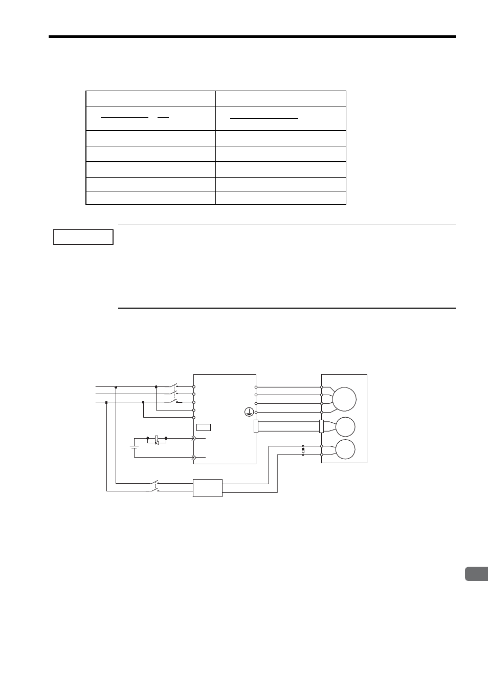
(1) Wiring Example
Use the SERVOPACK contact output signal /BK and the brake power supply to form a brake ON/OFF circuit.
The following diagram shows a standard wiring example.
Table 8.2 Calculation Method for Servomotor Stop Time
Using SI Units
Conventional Method
J
M
: Rotor moment of inertia (kgxm
2
)
GD
2
M
: Motor GD
2
(kgfxm
2
)
J
L
: Load moment of inertia (kgxm
2
)
GD
2
L
: Load inertia GD
2
(kgfxm
2
)
N
M
: Motor rotational speed (min
-1
)
N
M
: Motor rotational speed (r/min)
T
P
: Motor deceleration torque (Nxm)
T
P
: Motor deceleration torque (kgfxm)
T
L
: Load torque (Nxm)
T
L
: Load torque (kgfxm)
t
0
=
× (sec)
(T
P
+ T
L
)
(J
M
+ J
L
)
× N
M
2
π
60
t
0
= (sec)
(GD
2
M
+ GD
2
L
)
× N
M
375
× (T
P
+ T
L
)
IMPORTANT
Servomotor
with brake
SERVOPACK
Power supply
Red
Black
Blue or
yellow
White
BK-R Y: Brake control relay
∗ are the output terminals allocated with Pn50F.2.
M
BK
PG
U
V
W
CN2
AC
DC
BK-RY
BK-RY
+24V
L1/R
L2/S
L3/T
L1C/r
L2C/t
(/BK+)
(/BK-)
CN1
∗
∗
Brake power supply
Brake power supply Input voltage 200-V models: LPSE-2H01
Surge absorber model: CR50500BL (sold as Spark Quencher
manufactured by Okaya Electric Industries
Co., Ltd.)
Input voltage 100-V models: LPDE-1H01
R
S
T
Surge absorber