3 connection diagram – Yaskawa Sigma II Series SGMVH User Manual
Page 93
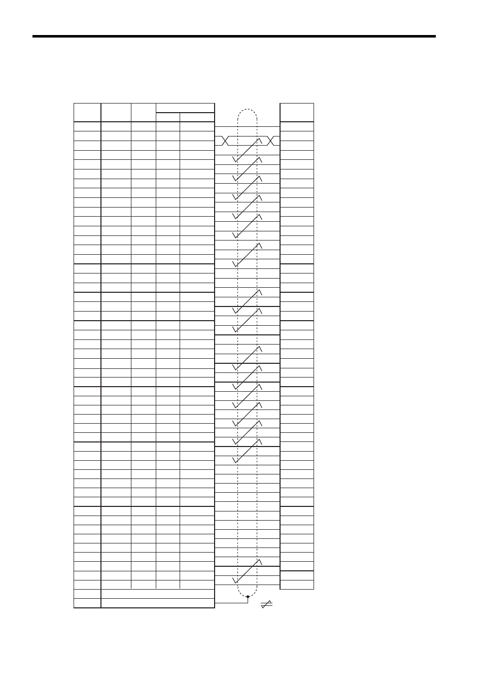
5 Specifications and Dimensional Drawings of Cables and Peripheral Devices
5.4.3 Connection Diagram
5-12
5.4.3 Connection Diagram
SG
SG
PL1
SEN
V-REF
SG
PULS
/PULS
T-REF
SG
SIGN
/SIGN
PL2
/CLR
CLR
−
−
PL3
PCO
/PCO
BAT(+)
BAT(-)
−
−
/V-CMP+
/V-CMP-
/TGON+
/TGON-
/S-RDY+
/S-RDY-
ALM+
ALM-
PAO
/PAO
PBO
/PBO
ALO1
ALO2
ALO3
/S-ON
/P-CON
P-OT
N-OT
/ALM-RST
/P-CL
/N-CL
+24VIN
PSO
/PSO
−
Host controller end
Pin No.
Lead
Color
Signal
Marking
Color
1
2
3
4
5
6
7
8
9
10
11
12
13
14
15
16
17
18
19
20
21
22
23
24
25
26
Lead
Marker No.
1
2
3
4
5
6
7
8
9
10
11
12
13
14
15
16
17
18
19
20
21
22
23
24
25
26
Orange
Gray
Orange
Gray
White
White
Yellow
Yellow
Pink
Pink
Orange
Orange
Gray
White
White
Gray
Yellow
Yellow
Pink
Pink
Orange
Orange
Gray
Gray
White
White
Red
Red
Black
Black
Red
Black
Red
Black
Red
Black
Red
Black
Red
Red
Black
Black
Red
Black
Red
Black
Red
Black
Red
Black
Red
Black
1
1
1
1
1
1
1
1
1
1
2
2
2
2
2
2
2
2
2
2
3
3
3
3
3
3
SERVOPACK end
27
28
29
30
31
32
33
34
35
36
37
38
39
40
41
42
43
44
45
46
47
48
49
50
Case
27
28
29
30
31
32
33
34
35
36
37
38
39
40
41
42
43
44
45
46
47
48
49
50
Yellow
Yellow
Pink
Pink
Orange
Orange
Gray
Gray
White
White
Yellow
Yellow
Pink
Pink
Orange
Orange
Gray
Gray
White
White
Yellow
Pink
Pink
Yellow
Red
Black
Red
Black
Red
Black
Red
Black
Red
Black
Red
Black
Red
Black
Red
Black
Red
Black
Red
Black
Red
Red
Black
Black
3
3
3
3
4
4
4
4
4
4
4
4
4
4
5
5
5
5
5
5
5
5
5
5
Shield
represents twisted-pair wires.
Dots