3) position control block diagram, Important – Yaskawa Sigma II Series SGMVH User Manual
Page 237
8 Operation
8.6.3 Position Reference
8-56
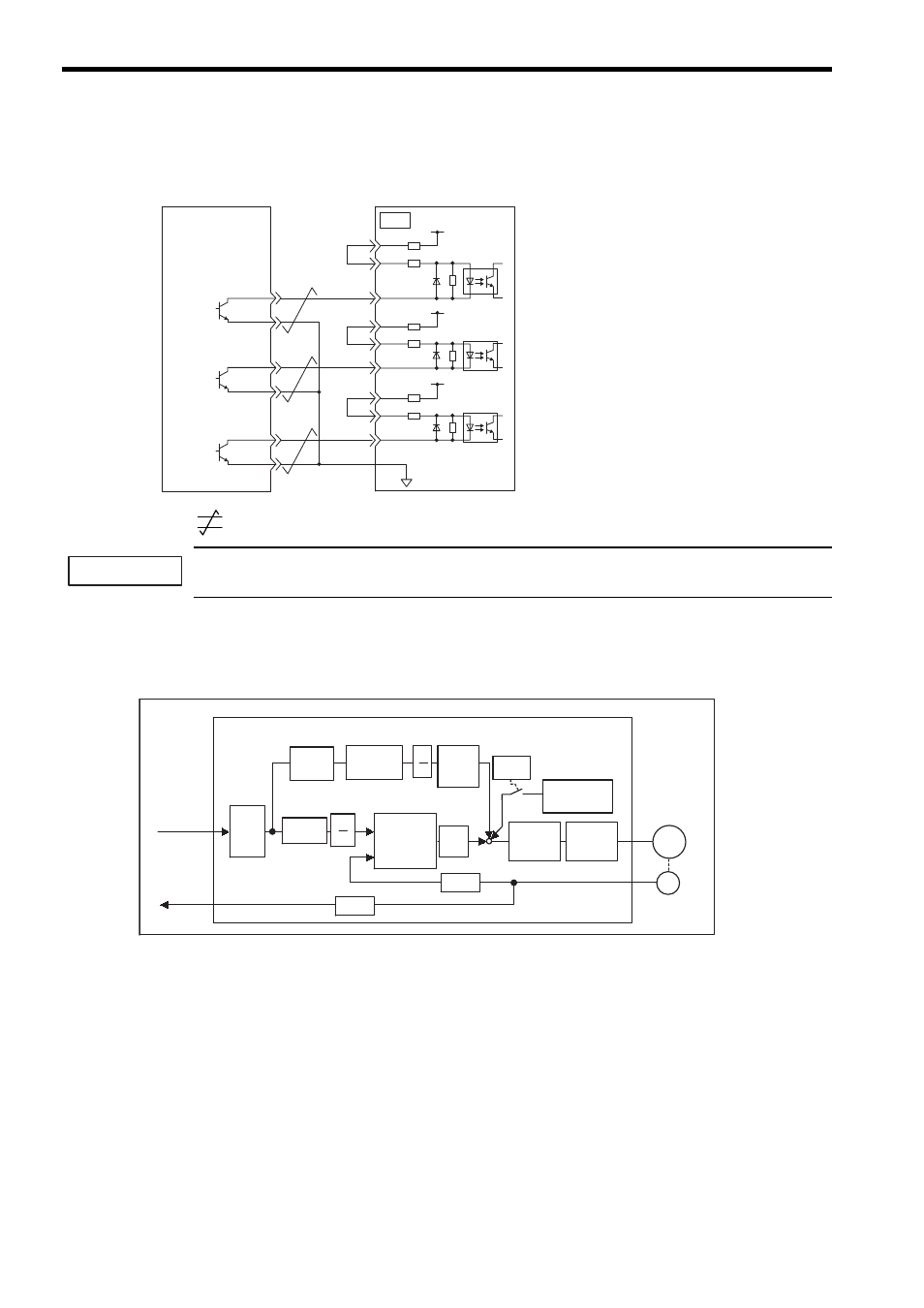
The SERVOPACK internal power supply can be used.
In this case, the circuit will not be isolated.
*
: Represents twisted-pair wires.
When the open-collector output is used, input signal noise margin lowers. When a position error caused by
the noise occurs, set the parameter Pn200.3 to 1.
(3) Position Control Block Diagram
A block diagram for position control is shown below.
SERVOPACK
Photocoupler
Host controller
CN1
7
3
8
1
14
15
12
11
13
18
/PULS
SIGN
/SIGN
CLR
/CLR
PULS
PL1
PL2
PL3
150
Ω
1 k
Ω
+12 V
∗
Tr1
1.5 V max.
at ON
IMPORTANT
Kp
M
Pn201
Pn204
Pn202
Pn203
+
-
Pn102
Pn203
Pn202 Pn10A
Pn107
Pn109
PG
Pn200.0
Pn108
B
A
B
A
+
+ +
Differ-
ential
Smoothing
Error
counter
Feed-
forward
Feed-for-
ward fil-
ter time
constant
Bias
Speed
loop
Current
loop
Dividing
Servomotor
Reference
pulse
PG signal
output
SERVOPACK (in position control)
Encoder
Bias adding
width
× 4
× 4
× 2
× 1
- Tag Generator (30 pages)
- MP3300iec (82 pages)
- 1000 Hz High Frequency (18 pages)
- 1000 Series (7 pages)
- PS-A10LB (39 pages)
- iQpump Micro User Manual (300 pages)
- 1000 Series Drive Option - Digital Input (30 pages)
- 1000 Series Drive Option - CANopen (39 pages)
- 1000 Series Drive Option - Analog Monitor (27 pages)
- 1000 Series Drive Option - CANopen Technical Manual (37 pages)
- 1000 Series Drive Option - CC-Link (38 pages)
- 1000 Series Drive Option - CC-Link Technical Manual (36 pages)
- 1000 Series Drive Option - DeviceNet (37 pages)
- 1000 Series Drive Option - DeviceNet Technical Manual (81 pages)
- 1000 Series Drive Option - MECHATROLINK-II (32 pages)
- 1000 Series Drive Option - Digital Output (31 pages)
- 1000 Series Drive Option - MECHATROLINK-II Technical Manual (41 pages)
- 1000 Series Drive Option - Profibus-DP (35 pages)
- AC Drive 1000-Series Option PG-RT3 Motor (36 pages)
- Z1000U HVAC MATRIX Drive Quick Start (378 pages)
- 1000 Series Operator Mounting Kit NEMA Type 4X (20 pages)
- 1000 Series Drive Option - Profibus-DP Technical Manual (44 pages)
- CopyUnitManager (38 pages)
- 1000 Series Option - JVOP-182 Remote LED (58 pages)
- 1000 Series Option - PG-X3 Line Driver (31 pages)
- SI-EN3 Technical Manual (68 pages)
- JVOP-181 (22 pages)
- JVOP-181 USB Copy Unit (2 pages)
- SI-EN3 (54 pages)
- SI-ET3 (49 pages)
- MECHATROLINK-III (35 pages)
- EtherNet/IP (50 pages)
- SI-EM3 (51 pages)
- 1000-Series Option PG-E3 Motor Encoder Feedback (33 pages)
- 1000-Series Option SI-EP3 PROFINET (56 pages)
- PROFINET (62 pages)
- AC Drive 1000-Series Option PG-RT3 Motor (45 pages)
- SI-EP3 PROFINET Technical Manual (53 pages)
- A1000 Drive Option - BACnet MS/TP (48 pages)
- 120 Series I/O Modules (308 pages)
- A1000 12-Pulse (92 pages)
- A1000 Drive Software Technical Manual (16 pages)
- A1000 Quick Start (2 pages)
- JUNMA Series AC SERVOMOTOR (1 page)
- A1000 Option DI-101 120 Vac Digital Input Option (24 pages)