2 online autotuning, 3 manual tuning, 1 explanation of servo gain – Yaskawa Sigma II Series SGMVH User Manual
Page 264
9 Adjustments
9.3.1 Explanation of Servo Gain
9-4
9.2 Online Autotuning
Online autotuning functions cannot be used for SERVOPACKs of 22 kW or more.
9.3 Manual Tuning
9.3.1 Explanation of Servo Gain
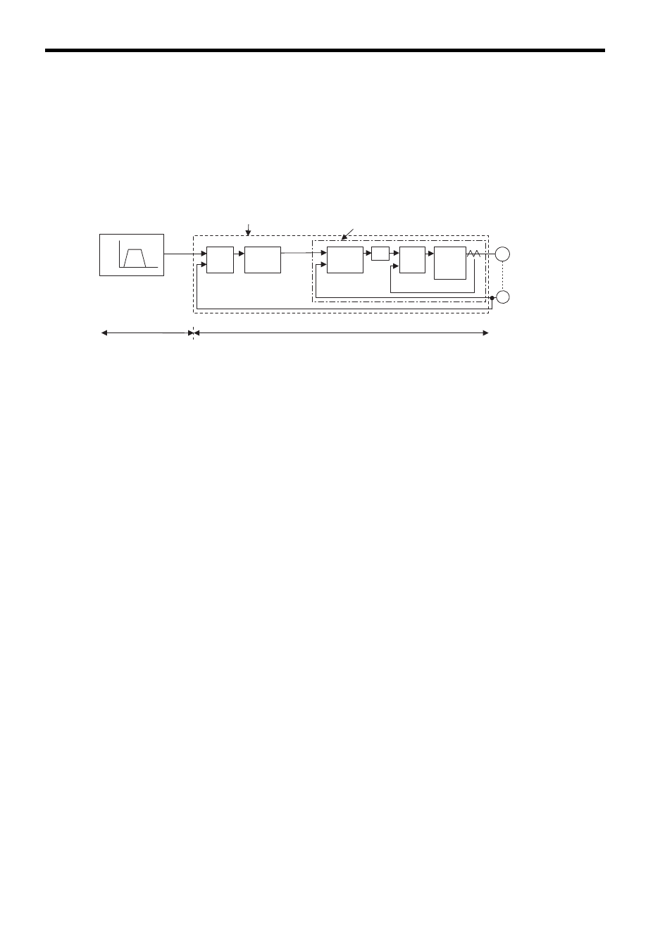
The block diagram for position control is as follows:
To adjust the servo gain manually, understand the configuration and characteristics of the SERVOPACK and
adjust the servo gain parameters one by one. If one parameter is changed, it is almost always necessary to adjust
the other parameters. It will also be necessary to make preparations such as setting up a measuring instrument to
monitor the output waveform from the analog monitor.
The SERVOPACK has three feedback loops (i.e., position loop, speed loop, and current loop). The innermost
loop must have the highest response and the middle loop must have higher response than the outermost. If this
principle is not followed, it will result in vibration or responsiveness decreases.
The SERVOPACK is designed to ensure that the current loop has good response performance. The user need to
adjust only position loop gain and speed loop gain.
Encoder
Position control loop
Speed control loop
Speed
Speed pattern
Time
Move
reference
Error
counter
Position
loop
gain
Kp
Speed
control
section
Kv
Ti
+
-
Current
control
section
Electric
power
converting
Section
Servomotor
M
PG
Position loop
SERVOPACK
Host controller
(provided by user)
Kp
Position Loop Gain (Pn102㧕
Kv
Speed Loop Gain㧔Pn100㧕
Ti
Speed Loop Integral Time
Tf
Torque Reference Filter Time
+
-
+
-
Speed
reference
Speed loop
Current loop
Tf
Constant (Pn101)
Constant (Pn401)