3 mechanical tolerance, 4 direction of servomotor rotation, 5 impact resistance – Yaskawa Sigma II Series SGMVH User Manual
Page 49: 6 vibration resistance
3 Servomotor Specifications and Dimensional Drawings
3.3.3 Mechanical Tolerance
3-14
3.3.3 Mechanical Tolerance
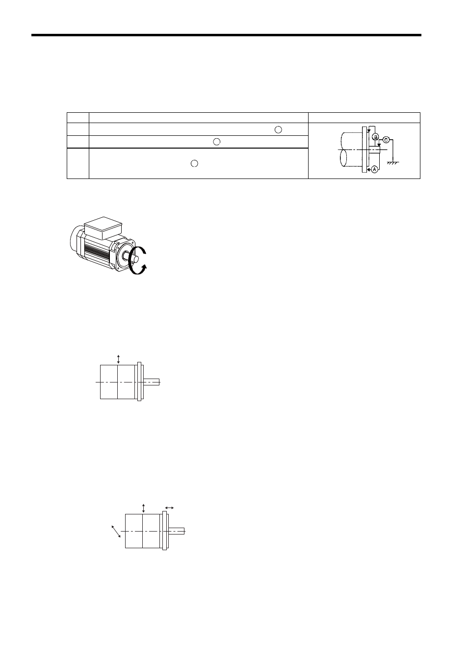
The following table shows tolerances for the servomotor’s output shaft and installation area. For more details on
tolerances, refer to the dimensional drawing of the individual servomotor.
3.3.4 Direction of Servomotor Rotation
Positive rotation of the servomotor is counterclockwise when viewed from the load.
3.3.5 Impact Resistance
Mount the servomotor with the axis horizontal. The servomotor will withstand the following vertical impacts:
• Impact acceleration: 490 m/s
2
• Impact occurrences: 2
3.3.6 Vibration Resistance
Mount the servomotor with the axis horizontal. The servomotor will withstand the following vibration accelera-
tion in three directions: Vertical, side to side, and front to back. The amount of vibration the servomotor endures
will vary depending on the application. Check the vibration acceleration being applied to your servomotor for
each application.
• Vibration acceleration: 24.5 m/s
2
Tolerance T. I. R. (Total Indicator Reading)
Reference Diagram
A
Perpendicularity between the flange face and output shaft
: 0.05
B
Mating concentricity of the flange O.D.
: 0.025
C
Run-out at the end of the shaft
: 0.03
A
B
C
Positive direction
Vertical
Horizontal shaft
Impact applied to the servomotor
Impact applied to the servomotor
Vertical
Front to back
Horizontal shaft
Side to side