4) output signal selection – Yaskawa Sigma II Series SGMVH User Manual
Page 243
8 Operation
8.6.8 Reference Pulse Input Multiplication Switching Function
8-62
Note: After changing the setting, turn OFF the power and ON again to enable the new setting.
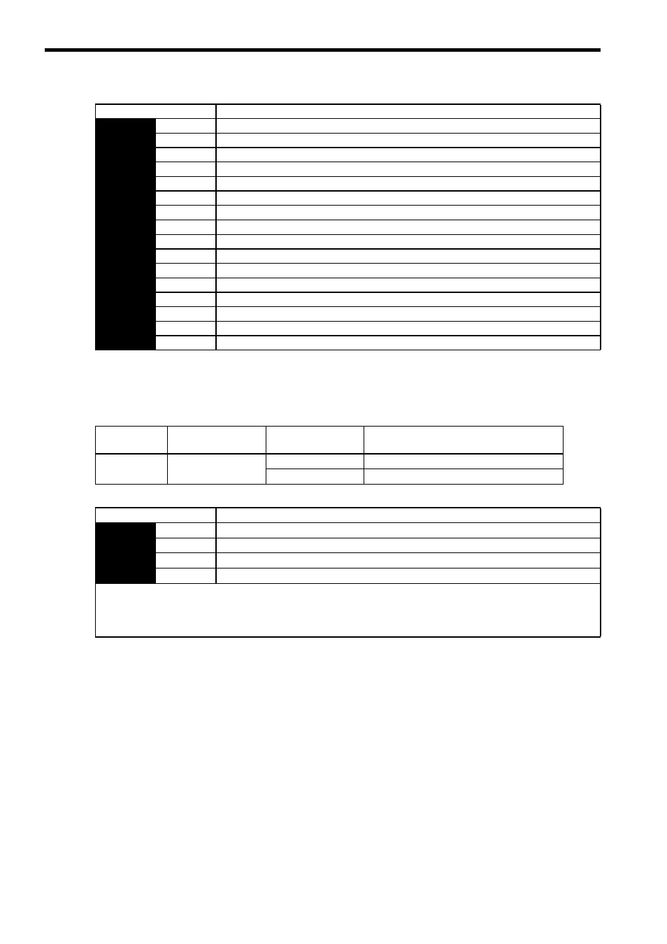
(4) Output Signal Selection
The /PSELA signal is the output signal that indicates if switching for reference pulse input multiplication is
enabled by /PSEL signal or not.
The /PSELA signal can’t be used with the factory setting. Allocate the /PSELA output signal.
Note: After changing the setting, turn OFF the power and ON again to enable the new setting.
Parameter
Description
Pn513
n.0
Input signal from CN1-40 is ON (high level): Enabled
n.1
Input signal from CN1-41 is ON (high level): Enabled
n.2
Input signal from CN1-42 is ON (high level): Enabled
n.3
Input signal from CN1-43 is ON (high level): Enabled
n.4
Input signal from CN1-44 is ON (high level): Enabled
n.5
Input signal from CN1-45 is ON (high level): Enabled
n.6
Input signal from CN1-46 is ON (high level): Enabled
n.7
Sets the signal ON.
n.8
Sets the signal OFF. (Factory setting)
n.9
Input signal from CN1-40 is OFF (low level): Enabled
n.A
Input signal from CN1-41 is OFF (low level): Enabled
n.B
Input signal from CN1-42 is OFF (low level): Enabled
n.C
Input signal from CN1-43 is OFF (low level): Enabled
n.D
Input signal from CN1-44 is OFF (low level): Enabled
n.E
Input signal from CN1-45 is OFF (low level): Enabled
n.F
Input signal from CN1-46 is OFF (low level): Enabled
Signal Name
Connector Pin
Number
Setting
Meaning
/PSELA
Signal allocation not
required
ON (low level)
Enabled when the /PSEL signal turns ON.
OFF (high level)
Disabled when the /PSEL signal turns OFF.
Parameter
Meaning
Pn510
n.0
Disabled (/PSELA output signal is not used.)
n.1
Outputs the /PSELA signal from the CN1-25, 26 output terminal.
n.2
Outputs the /PSELA signal from the CN1-27, 28 output terminal
n.3
Outputs the /PSELA signal from the CN1-29, 30 output terminal.
For the factory settings, the pins CN1-25 to CN1-30 are allocated for other output signals. If multiple signals are allocated
to the same output terminal, signals are output with OR logic. To enable only the /PSELA output signal, allocate the other
signals to other output terminals or disable the other signals.
Refer to 7.3.3 Output Circuit Signal Allocation
for the allocation of output signals.