Yaskawa Sigma II Series SGMVH User Manual
Page 329
11.3 List of Parameters
11-27
11
Appendix
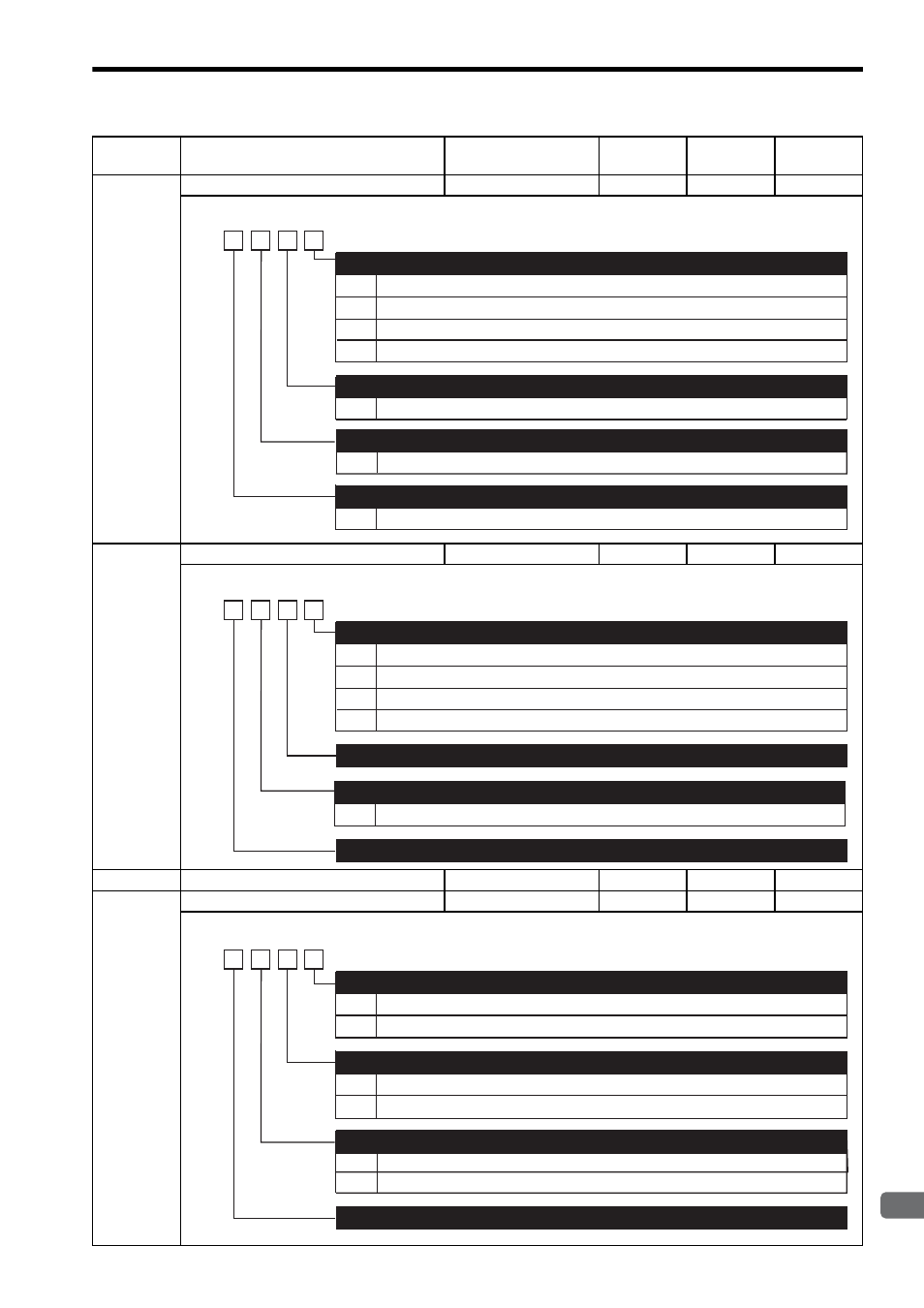
Pn50F
Output Signal Selections 2
−
−
0000
After restart
Pn510
Output Signal Selections 3
−
−
0000
After restart
Pn511
Reserved (Do not change)
−
−
8888
Immediately
Pn512
Output Signal Reversal Settings
−
−
0000
After restart
Parameter
No.
Name
Setting Range
Unit
Factory
Setting
Setting
Validation
0
1
2
3
0 to 3
Disabled (the above signal is not used.)
Outputs the signal from CN1-25, -26 output terminal.
Outputs the signal from CN1-27, -28 output terminal.
Outputs the signal from CN1-29, -30 output terminal.
Same as /CLT
Same as /CLT
Same as /CLT
Torque Limit Detection Signal Mapping (/CLT)
Speed Limit Detection Signal Mapping (/VLT)
Brake Interlock Signal Mapping (/BK)
4th
digit
3rd
digit
2nd
digit
1st
digit
n.
0 to 3
0 to 3
Warning Signal Mapping (/WARN)
0
1
2
3
Disabled (the above signal is not used.)
Outputs the signal from CN1-25 or -26 terminals.
Outputs the signal from CN1-27 or -28 terminals.
Outputs the signal from CN1-29 or -30 terminals.
Near Signal Mapping (/NEAR)
4th
digit
3rd
digit
2nd
digit
1st
digit
n.
Reserved (Do not change)
Reserved (Do not change)
Same as /NEAR
0 to 3
Reference Pulse Input Multiplication Change Output Signal Mapping (/PSELA)
0
1
0
1
0
1
Output signal is not reversed.
Output signal is reversed.
Output signal is not reversed.
Output signal is reversed.
Output signal is not reversed.
Output signal is reversed.
Output Signal Reversal for CN1-25 or -26 Terminals
4th
digit
3rd
digit
2nd
digit
1st
digit
n.
Output Signal Reversal for CN1-27 or -28 Terminals
Output Signal Reversal for CN1-29 or -30 Terminals
Reserved (Do not change)