2 allowable radial and thrust loads, Series, 2) 800 min – Yaskawa Sigma II Series SGMVH User Manual
Page 48
3.3 Mechanical Specifications of Servomotors
3
Servomotor Specifications and Dimensional Drawings
3-13
3.3.2 Allowable Radial and Thrust Loads
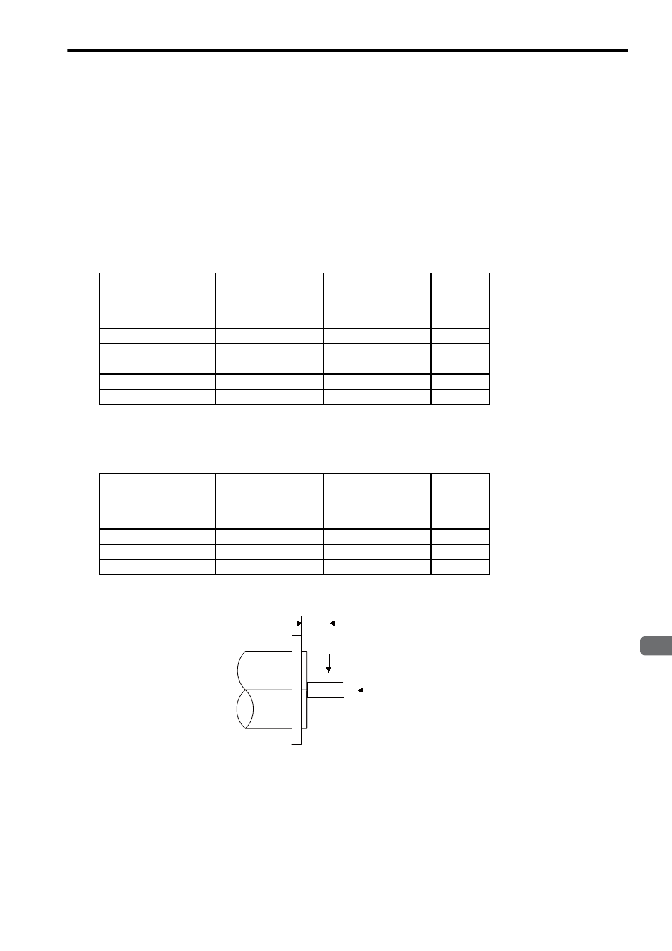
The following table shows the allowable loads applied to the SGMVH servomotor shaft end.
Design the mechanical system so radial and thrust loads applied to the servomotor shaft end during operation
falls within the ranges shown in the following table.
Note that even when using a servomotor below the allowable radial load, the following imbalance or the loads
may damage the bearings.
• The imbalance of parts that are connected to the shaft end
• Rotating loads generated by unmatched concentricity, when the bearing is attached to the extended shaft
end.
(1) 1500 min
-1
Series
Note: Allowable radial and thrust loads shown above are the maximum values that could be
applied to the shaft end from motor torque or other loads.
(2) 800 min
-1
Series
Note: Allowable radial and thrust loads shown above are the maximum values that could be
applied to the shaft end from motor torque or other loads.
Servomotor Model
SGMVH-
Allowable Radial Load
Fr [N]
Allowable Thrust
Load
Fs [N]
LR
[mm]
2BAB, 2BDB
5880
2156
100
3ZAB, 3ZDB
6272
2156
100
3GAB, 3GDB
7448
2156
100
4EDB
7840
2156
100
5EDB
8428
2156
110
7EDB
10100
2156
120
Servomotor Model
SGMVH-
Allowable Radial Load
Fr [N]
Allowable Thrust
Load
Fs [N]
LR
[mm]
2BAD, 2BDD
7448
2156
100
3ZAD, 3ZDD
8428
2156
110
3GAD, 3GDD
8428
2156
110
4EDD
10100
2156
120
LR
Fr
Fs