10 control mode selection, 1 setting parameters, 2 switching the control mode – Yaskawa Sigma II Series SGMVH User Manual
Page 257
8 Operation
8.10.1 Setting Parameters
8-76
8.10 Control Mode Selection
The methods and conditions for switching SERVOPACK control modes are described below.
8.10.1 Setting Parameters
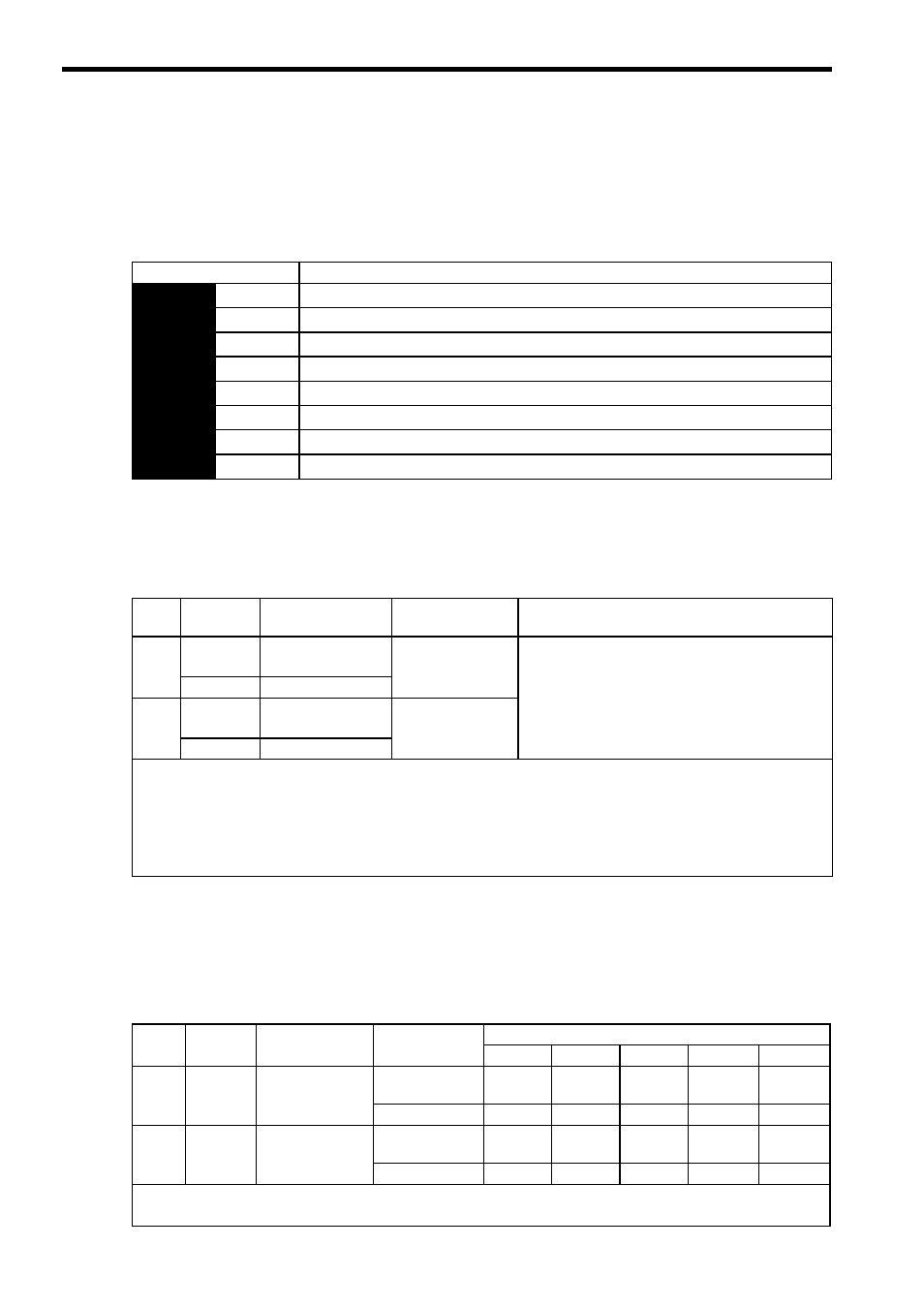
The following combinations of control modes can be selected according to the application at hand.
8.10.2 Switching the Control Mode
(1) Switching Internally Set Speed Control (Pn000.1 = 4, 5, or 6)
With the sequence input signals in the factory setting (Pn50A = n.0), the control mode will switch when
both /P-CL (/SPD-A) and /N-CL (/SPD-B) signals are OFF (high level).
(2) Switching Other Than Internally Set Speed Control (Pn000.1 = 7, 8, 9, A, or B)
Use the following signals to switch control modes. The control modes switch as shown below for each of the sig-
nal states indicated.
When changing the sequence input signal from the factory setting (Pn50A = n.1), allocate the /C-SEL to
an input terminal and change modes with the /C-SEL signal. In this case, input a speed reference (analog voltage
reference) for speed control, and a position reference (pulse train reference) for position control.
Parameter
Control Method
Pn000
n.4
Internally set speed control (contact reference)
⇔
Speed control (analog voltage reference)
n.5
Internally set speed control (contact reference)
⇔
Position control (pulse train reference)
n.6
Internally set speed control (contact reference)
⇔
Torque control (analog voltage reference)
n.7
Position control (pulse train reference)
⇔
Speed control (analog voltage reference)
n.8
Position control (pulse train reference)
⇔
Torque control (analog voltage reference)
n.9
Torque control (analog voltage reference)
⇔
Speed control (analog voltage reference)
n.A
Speed control (analog voltage reference)
⇔
Zero clamp
n.B
Position control (pulse train reference)
⇔
Position control (inhibit)
Type
Signal
Name
Connector
Pin Number
Setting
Meaning
Input
/P-CL
CN1-45
(Factory setting)
OFF (high level)
Switches control mode.
(/SPD-A)
Must be allocated
Input
/N-CL
CN1-46
(Factory setting)
OFF (high level)
(/SPD-B)
Must be allocated
Input Signal Selection
The following two types of control mode selection are available for switching from internally set speed control:
• Switching with the /P-CL and /N-CL input signals (pins allocated in factory setting)
• Switching with the /SPD-A and /SPD-B input signals
When using /SPD-A and /SPD-B, they must be allocated with parameter Pn50C. Refer to 7.3.2 Input Circuit Signal Alloca-
tion
.
Type
Signal
Name
Connector
Pin Number
Setting
Pn000 Setting
n.7 n.8 n.9 n.A n.B
Input
/P-CON
CN1-41
(Factory setting)
ON (low level)
Speed
Torque
Speed
Zero
clamp
Inhibit
OFF (high level)
Position
Position
Torque
Speed
Position
Input
/C-SEL
Must be allocated
ON (low level)
Speed
Torque
Speed
Zero
clamp
Inhibit
OFF (high level)
Position
Position
Torque
Speed
Position
The control mode can be switched with either /P-CON or /C-SEL.
When using the /C-SEL signal, the input signal must be allocated. Refer to 7.3.2 Input Circuit Signal Allocation
.