2 setting the electronic gear, 1) number of encoder pulses, 2) electronic gear – Yaskawa Sigma II Series SGMVH User Manual
Page 232: Sgmvh- (servomotor model)
8.6 Operating Using Position Control
8
Operation
8-51
8.6.2 Setting the Electronic Gear
(1) Number of Encoder Pulses
Note: For details on reading servomotor model numbers, refer to 2.1 Servomotor Model Designations.
The number of bits representing the resolution of the applicable encoder is not the same as the number of encoder signal
pulses (phases A and B). The number of bits representing the resolution is equal to the number of encoder pulses
× 4 (mul-
tiplier).
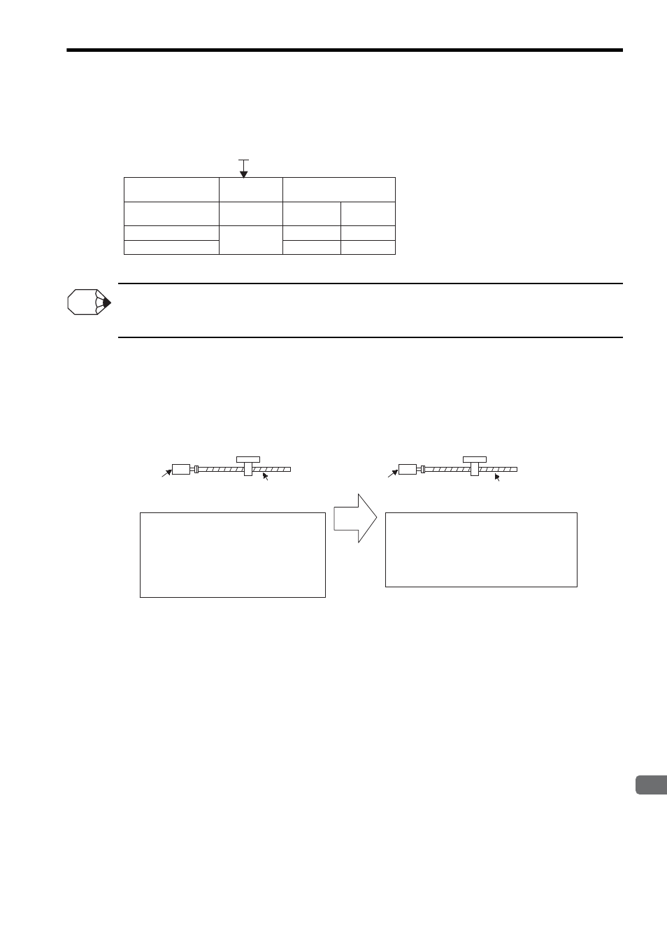
(2) Electronic Gear
The electronic gear enables the workpiece travel distance per input reference pulse from the host controller to be
set to any value. One reference pulse from the host controller, i.e., the minimum position data unit, is called a ref-
erence unit.
SGMVH-
(Servomotor model)
Encoder Type
Incremental
encoder
C
2
3
17 bits
17 bits
20 bits
32768
32768
262144
Absolute
encoder
No. of Encoder Pulses
(P/Rev)
Motor Model
Encoder Specifications
INFO
When the Electronic Gear
Is Not Used
When the Electronic Gear Is Used
Ball screw pitch: 6 mm
Workpiece
No. of encoder pulses: 2048 P/Rev
Reference unit: 1
μm
:
To move a workpiece 10 mm:
10
÷ 6 =1.6666 revolutions
2048
× 4 pulses is 1 revolution. Therefore,
1.6666
× 2048 × 4 = 13653 pulses
13653 pulses are input as reference pulses.
The equation must be calculated at the
host controller.
To move a workpiece 10 mm using reference units:
The reference unit is 1
μm. Therefore,
To move the workpiece 10 mm (10000
μm),
1 pulse = 1
μm, so
10000/1=10000 pulses.
Input 10000 pulses per 10 m
m of workpiece
movement.
Ball screw pitch: 6 mm
No. of encoder pulses: 2048 P/Rev
Workpiece
1 revolution is 6 mm. Therefore,